Parametric Options in Cross Section Editor
When creating a bridge in SOFiPLUS, it is most likely by using the “Computer-Aided Bridge Design” concept of SOFiSTiK for beams.
The main elements of this concept are the definition of an axis for the bridge alignment, placements to indicate any points of interest such as support or construction joints. And finally, the definition of variables, which is essential for parametric cross-sections.
In this post, you will learn about the different parametric options within the “SOFiPLUS Cross Section Editor”. I will explain the principles of the functionality and the workflow of the input with simple examples.
If you are new to SOFiSTiK and parametric modelling, I recommend reading the blog post Basics of Modelling a Parametric Beam Bridge.
Before we get into it, let’s look into the requirements to create a parametric cross-section.
There are a couple of things to consider when creating a parametric cross-section in SOFiPLUS.
First, you will have to have an axis and variables available in your project. Otherwise, the program cannot interpolate the different cross-sections based on the parametric information.
No Axis – No parametric model!
Second, you have to create the cross-section with the “Cross Section Editor” in SOFiPLUS. Assigning variables to standard cross-section is simply not working.
With that out of the way, let’s get into it.
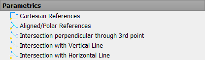
Parametric Options in “Cross Section Editor”
There are five options available to create a parametric cross-section
- Cartesian References
- Aligned/Polar Reference
- Intersection Perpendicular through 3rd Point
- Intersection with Vertical Line
- Intersection with Horizontal Line
You might think that the five options are not sufficient to create a parametric section. But trust me, you will not even need all these five.
One more last hint. Don’t forget to check the command line in AutoCAD when using the parametric options in “SOFiPLUS Cross Section Editor”. The command line shows instructions of any SOFiSTiK command and guides you through the required input.
Cartesian References
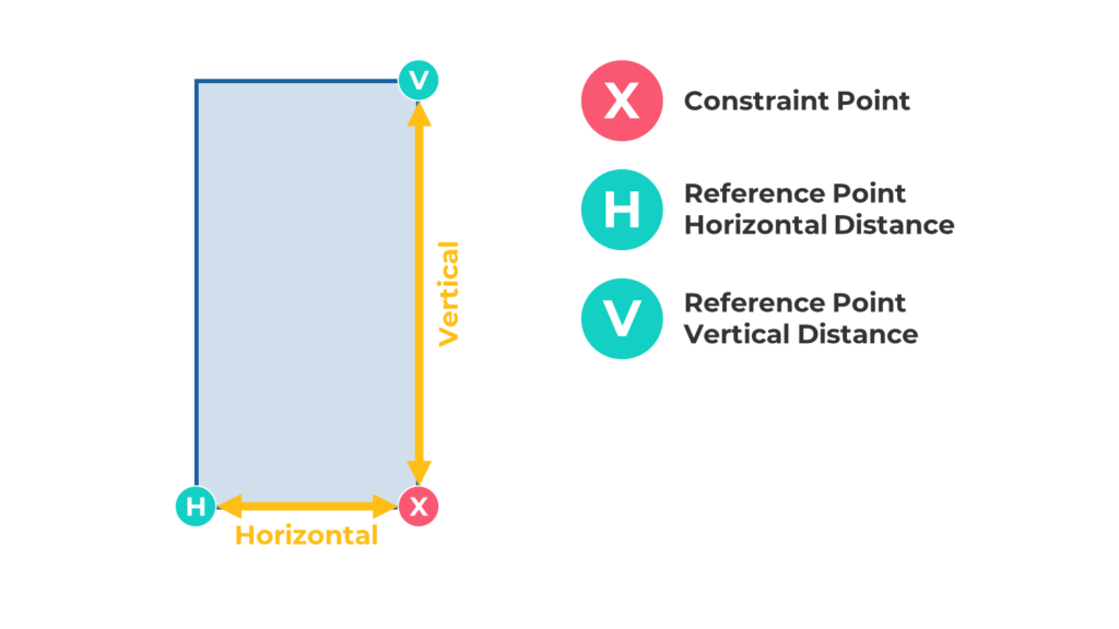
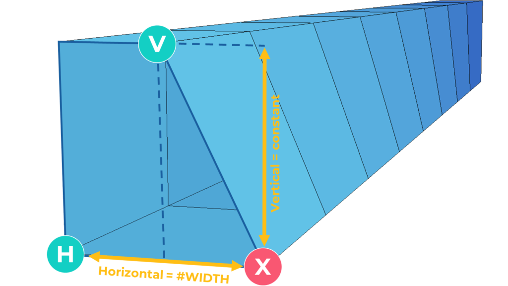
The “Cartesian References” is the simplest parametric option available in “Cross Section Editor”. And it is also the most used one. At least to my experience. You can cover most of the parametric requirements with it. The “Cartesian Reference” allows you to change the position of a point along a horizontal and vertical direction.
Step 1: Start the command “Cartesian References.”

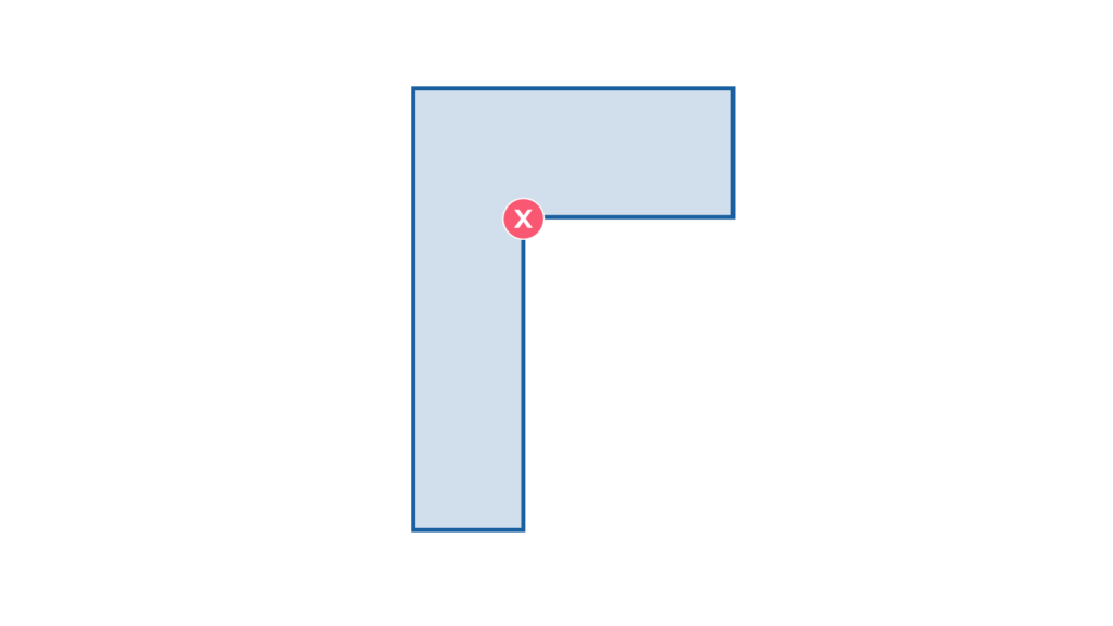
Step 2: Specify Constraint Point
The first point to select is the one that will change its position. Click straight on the point, for better accuracy, use the object snap.


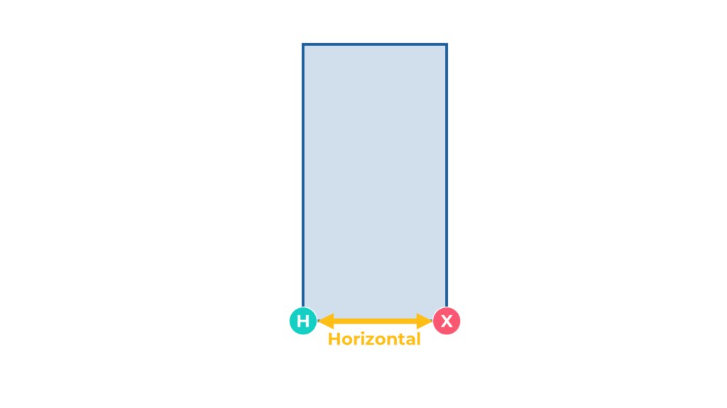
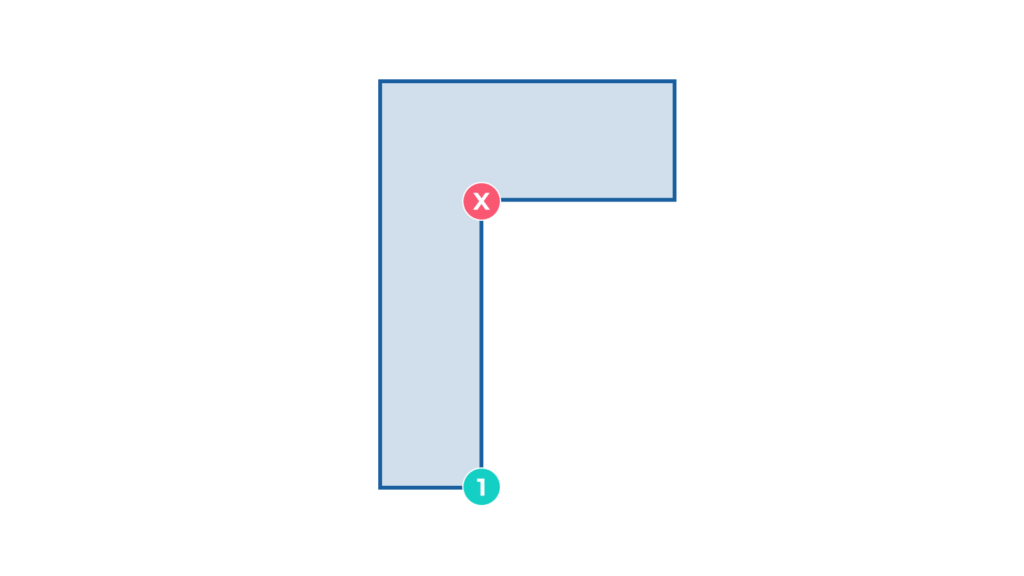
Step 3: Specify the Reference Point of the Horizontal Distance
Now select the reference point to which the horizontal distance should be referenced.

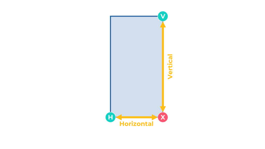
Step 4: Specify the Reference Point of the Vertical Distance
Similar to the horizontal distance, you have to select the point to which the vertical distance refers.

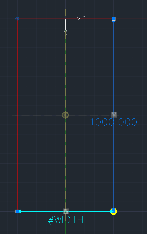
You should now see something similar in the Cross-Section Editor as shown in the image below.
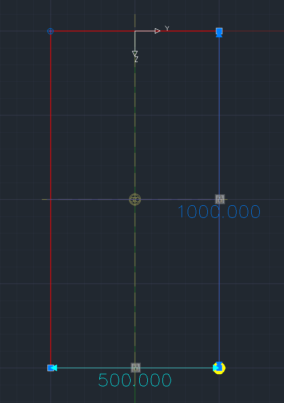
The program creates links between the “Constraint Point” and the “Reference Point(s)”. The numbers represent the actual horizontal and vertical distance. If you assign this cross-section to a structural line, the program doesn’t interpolate anything. The dimension of the cross-section will remain constant, as shown in the image.
Step 5: Assign the variable
Now it is time to transform the static cross-section finally to a parametric cross-section.
If you hover over the padlock icon, you’ll see the balloon tip saying that you can assign a value or formula for the distance.
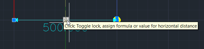
Go on and left-click on the padlock and start assigning the variable.
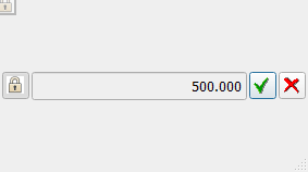
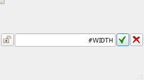
The new dialogue box shows the locked padlock, the actual distance, a green tick, and a red X.
The closed padlock means that the actual distance is used. We will change this in a second. The green tick confirms any changes, and the red X closes the input without saving the modifications.
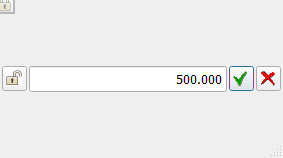
Left Click on the padlock, and the input of the value is unlocked to modify it.
Click in the text field and enter #. You’ll get a list of all available variables for this cross-section.
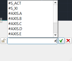
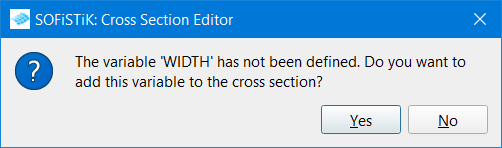
If you haven’t assigned the variable defined in the geometry axis yet, no worries, you can do this from this dialogue. In my example, I use the variable #WIDTH, and I have to enter #width.
When confirming the variable name – just hit Enter on your keyboard –another pop-up comes up. You can confirm it with Enter again. This pop confirms the assignment of the variable #width to the cross-section again. You will not get this pop-up if you have assigned the variable in the cross-section properties already.
The text of the horizontal distance – which shows 250 in the first place – changes to the variable name #WIDTH.
The final step, assigning the cross-section to the geometric axis and creating the calculation model.
Congratulations, you just created a parametric cross-section.
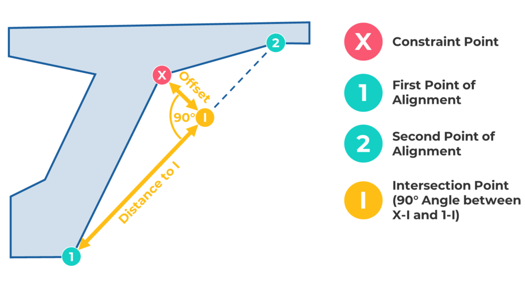
Aligned/Polar References
The “Align/Polar References” option is kind of similar to the “Cartesian References”. However, despite relying on the horizontal and vertical axis, it allows you to define the direction with two points.
Keep in mind the Offset direction of the “Constraint Point” to the alignment is always locked to a “Right Angle (90°)” at the “Intersection Point”.
Let’s look into the workflow of the “Aligned/Polar References”.
Step 1: Start the command “Aligned/Polar References”

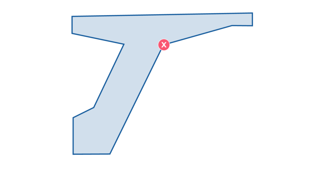
Step 2: Specify the Constraint Point
As before, this is the point that will change its location based on the parametric information you provided.

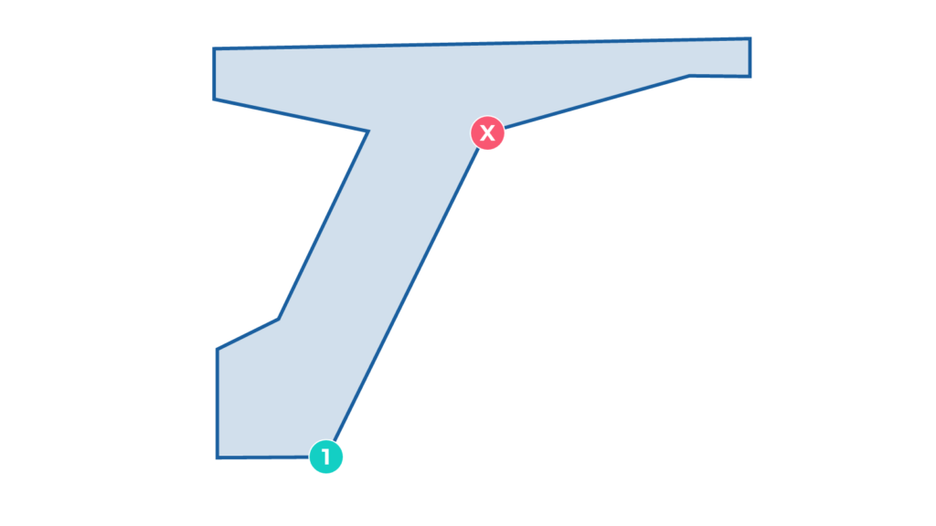
Step 3: Define the First Point of the Alignment
Now it is time to define the alignment for the reference line. In this step, you have to define the “First Point of Alignment”.

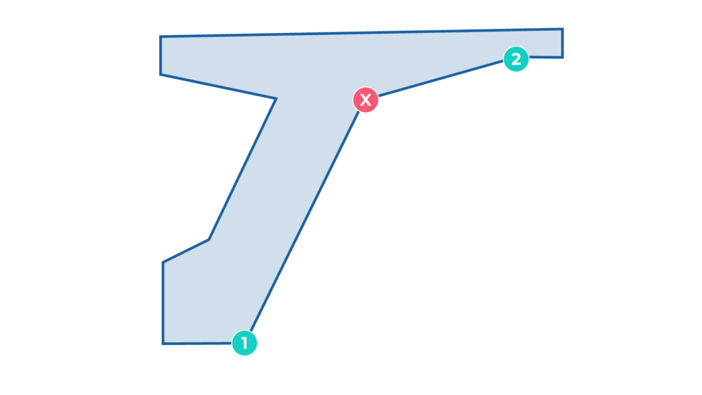
Step 4: Define the Second Point of the Alignment
To complete the alignment and define the “Second Point of Alignment”.

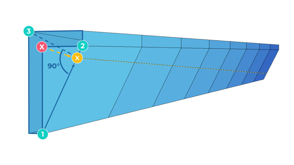
With the definition of the “Second Point of Alignment”, you should see something similar on the screen as shown in the image below.
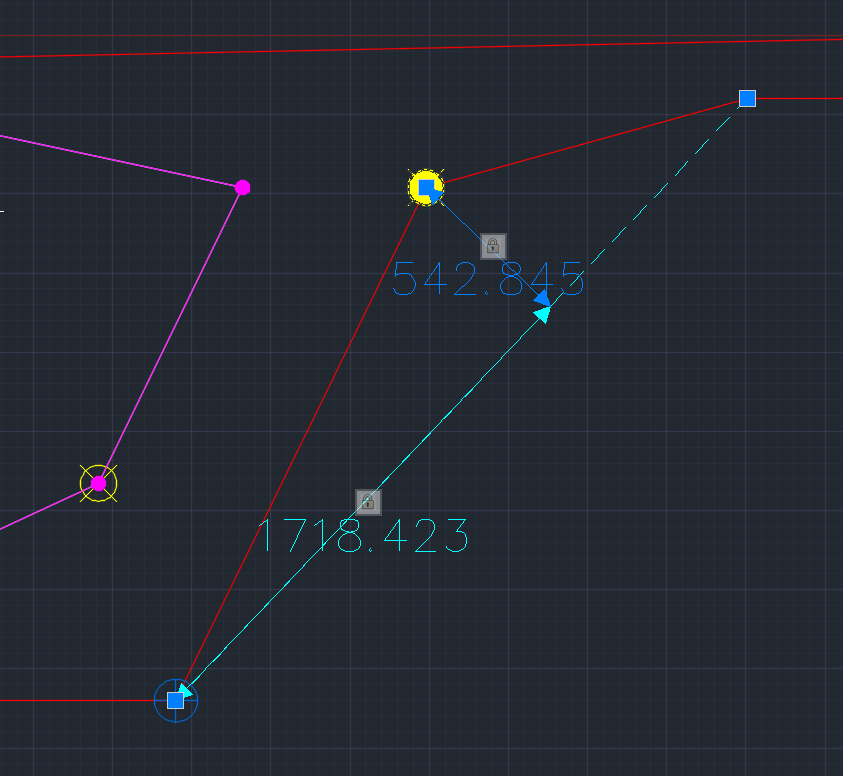
The program indicates quite nicely the meaning of all references and points. Distances represented with an arrow and the padlock can be assigned to a variable what brings me to the last step.
Step 5: Assign the variable
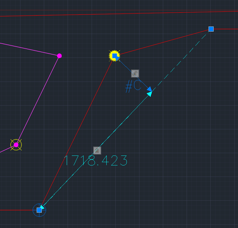
Assigning the variable values to the distance and offset works similar to the “Cartesian References”. Toggle the locked padlock and select the variable from the drop-down menu.
In my example, I assign variable #C to the “Offset” value only. Assigning a variable to the “Distance” or even to both values is of course possible.
Let’s have a look into the result of this parametric cross-section.
And the interpolated Cross Section in Result Viewer.
Intersection Perpendicular through 3rd Point
The “Intersection perpendicular through 3rd Point” option differs from the others by not allowing to assign a variable. It is more like a condition.
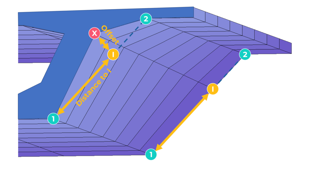
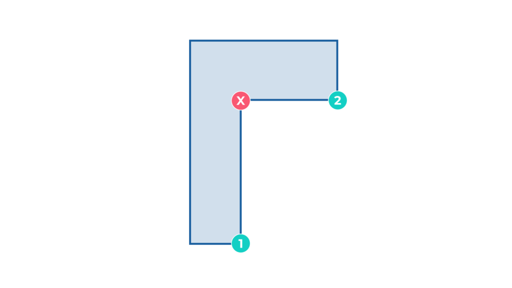
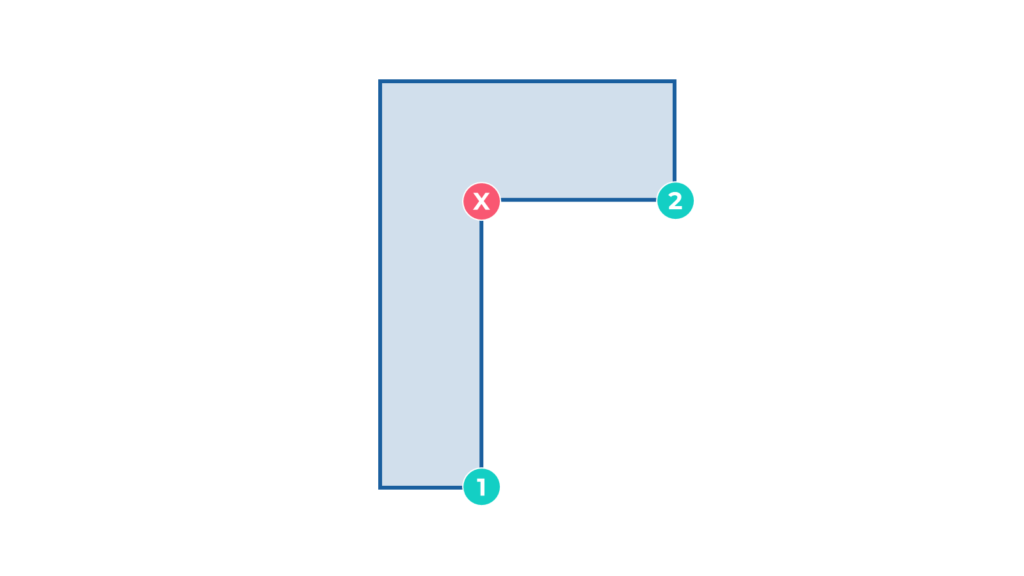
The option allows you to align the “Constraint Point” with the interaction of alignment and a perpendicular line through a third reference point.
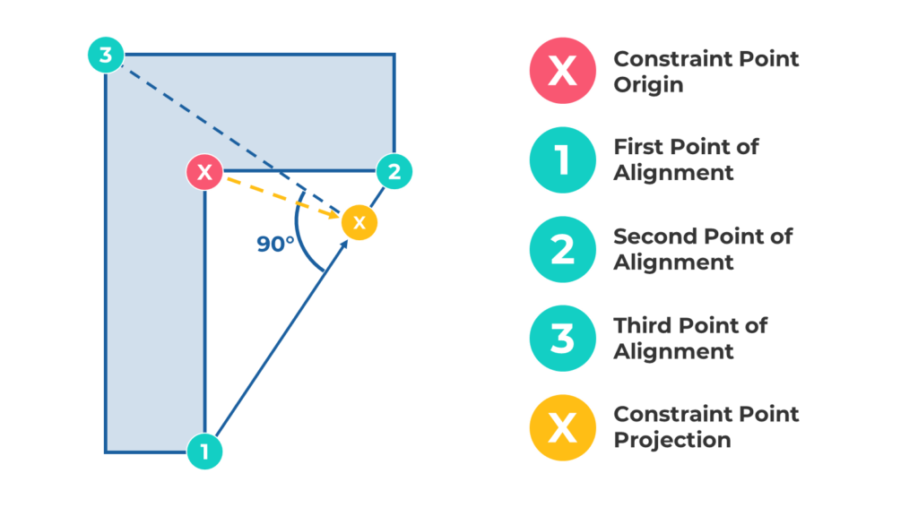
In the graphic above, you can see that the “Constraint Point” X changes its position in relation to the interaction of the connecting line 1-2 and the perpendicular line to it through the third reference point.
As it is not possible to assign a variable to this parametric option, you will not see any interpolation happening if this is the only condition in the cross-section.
There must be at least one parametric definition used in the cross-section. Otherwise, you won’t get any effect.
Let’s see how the workflow looks like for this parametric option.
Step 1: Start the command “Aligned/Polar References.”
Step 2: Specify the Constraint Point
Select the “Constraint Point” which shall change its location according to the defined condition.

Step 3: Define the First Point of the Alignment
The “First Point of Alignment” is the first of the connecting line on which the projected “Constraint Point” will change its position.

Step 4: Define the Second Point of the Alignment
The “Second Point of Alignment” completes the definition of the connecting line.

Step 5: Define the Third Point of Reference
The “Third Point” defines the perpendicular to the connecting line to which the “Constraint Point” will be projected.

After completing the selection of the “Third Point of Reference” you should see a similar representation of the condition on your screen as shown in the image below.
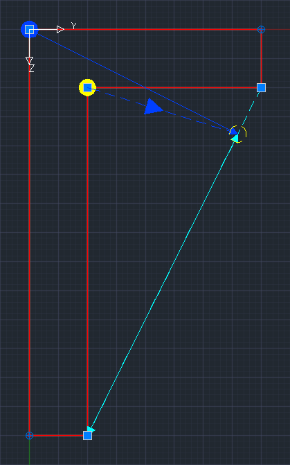
As mentioned earlier, this parametric option will not have any effect if there is no variable used in the cross-section.
To finally see any change, I assign a “Cartesian Reference” to the Point in the origin of the cross-section to change its position in the positive Z direction.
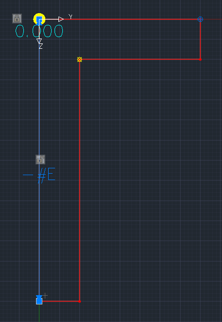
Let’s have a look at what happens to the cross-section now.
Interpolated Cross Section in Result Viewer
Intersection with Vertical Line
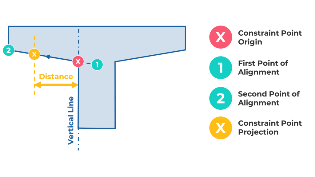
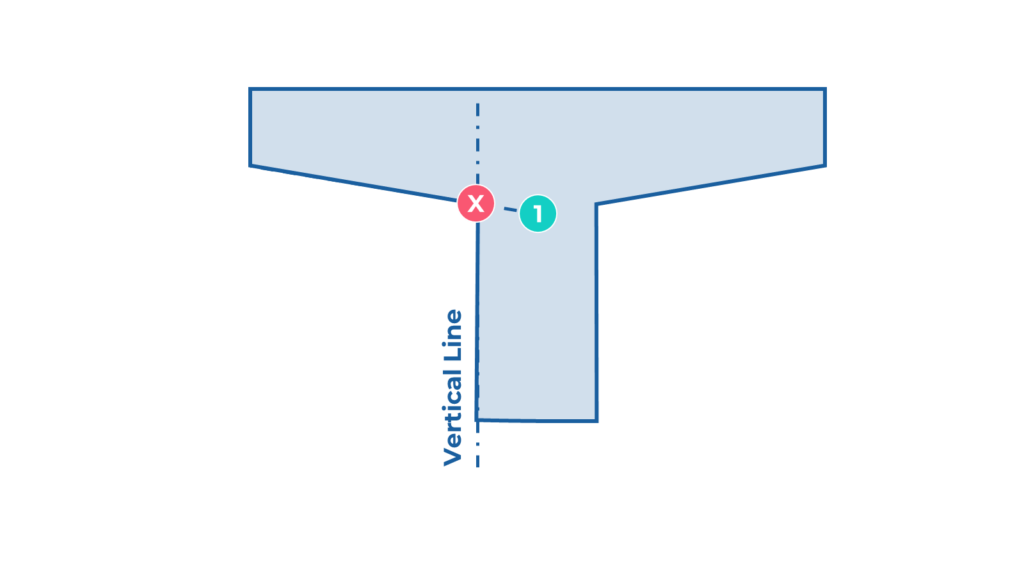
The parametric option “Intersection with vertical Line” makes working with non-orthogonal cross-section geometries so much more fun. The principle is simple. The parametric information is referred to a vertical line, while two points define the path for the movement of the “Constraint Point”.
The workflow is straightforward as the ones before.
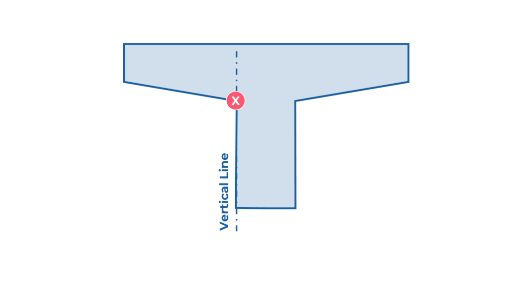
Step 1: Start the command “Intersection with Vertical Line”

Step 2: Specify the Constraint Point
Select the “Constraint Point” which will change its location referring to the vertical line.

Step 3: Define the First Point of the Alignment
The “First Point of Alignment” is the first of two points that define the path of the “Constraint Point” movement.
The input requires a “Polygon Point”, “Geometry Point” or “Stress Point”. If you click on something else, the program creates a “Geometry Point” for you automatically.

Step 4: Define the Second Point of the Alignment
Complete the path by selecting the “Second Alignment Point”.
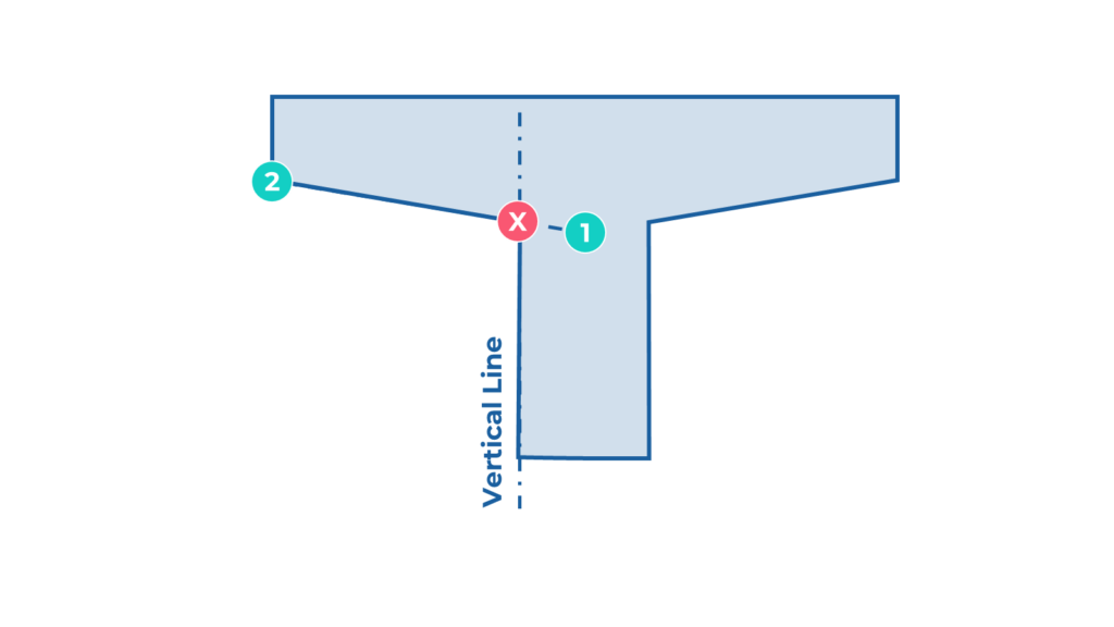

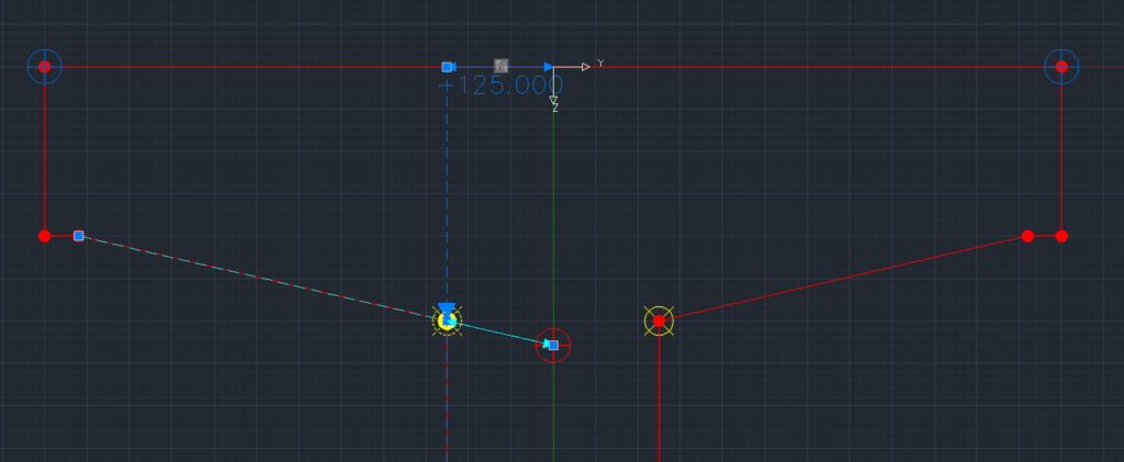
After confirming the “Second Alignment Point” you should see something similar as shown in the image below.
To make the constant horizontal value a parametric one, just unlock the padlock and assign a variable name. In my case, it is the variable #WEB_WIDTH. A similar process as we did several times before.
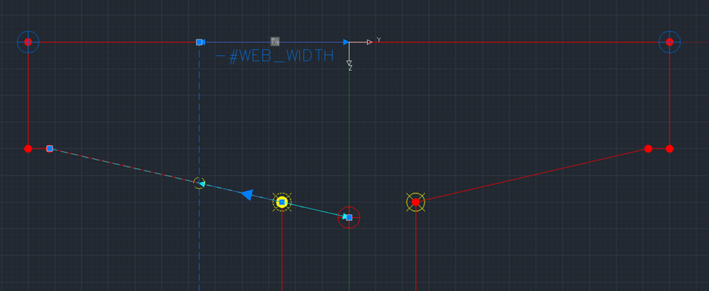
Check below the result in “Result Viewer” after assigning the cross-section to a geometric axis and exporting it.
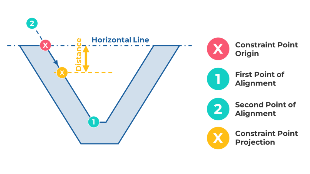
Intersection with Horizontal Line
The “Interaction with Horizontal Line” option works similarly to the “Interaction with Vertical Line”. The path of the movement can be defined with two points. Its intersection is with a horizontal line instead of a vertical line. The steps to take are entirely the same.
Step 1: Start the command “Intersection with Horizontal Line”

Step 2: Specify the Constraint Point

Step 3: Define the First Point of the Alignment
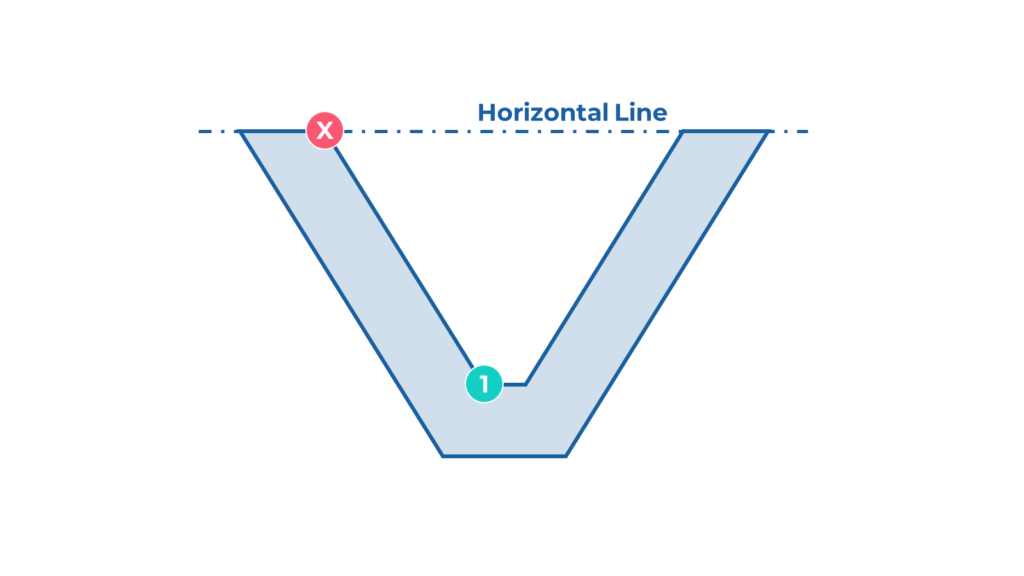

Step 4: Define the Second Point of the Alignment
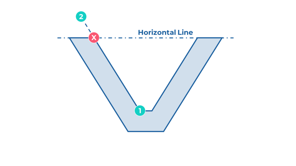

After confirming the “Second Alignment Point” you should see something similar as in the below image.
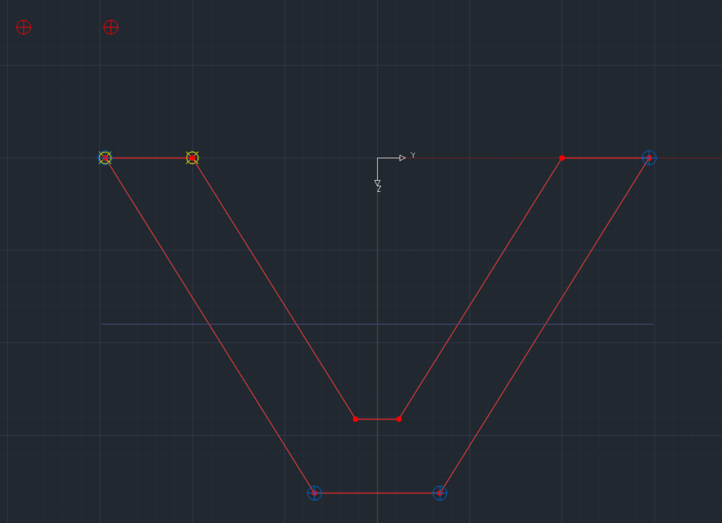
To make it a parametric cross-section assign a variable by unlocking the padlock. I use variable #F in my example.
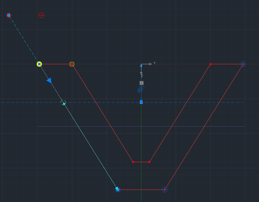
Let’s see what happens to this cross-section definition after assigning and exporting it. I use again “Result Viewer” to check the changes.
Interpolated Cross Section in Result Viewer
Wrap Up
Creating a parametric cross-section might not always be something you need to consider in your project. However, when creating a beam bridge model, the chances a quite high, you have to.
Having the parametric modelling capability by using the “Computer Aided Bridge Design Concept” is a huge benefit. Because of the dynamic axis and it links to the bridge members, and the parametric cross-section capabilities.
The parametric options in the “Cross Section Editor” allow you to define a cross-section in a way to be well prepared against any changes along the bridge alignment. Its straightforward input and ease of use regarding modifications of the geometry enhance the visual editor even more.
Download the examples and test the parametric options in SOFiPLUS Cross Section Editor yourself.
Software version: SOFiSTiK FEA 2020-4.
