The Complex Nature of Bridge Design
The new SOFiSTiK Version 2018 was released.
New tools are required to fully take advantage of the benefits of bridge information modelling, reported by Georg Pircher and Jakub Bielski.
The concept of Building Information Modelling (BIM) is the next step of digitalisation in the construction industry. The advantages of the implementation of BIM in design workflows have already been proven by a number of practices and pilot projects. Although an advanced application and further development of BIM has taken place in the Building Industry, the infrastructure sector wants to follow the trend and shows interest in obtaining the benefits of BIM practice.
Authorities and ministries back this movement. Being aware of the capabilities and potential of BIM design, the government of United Kingdom decided to encourage entrepreneurs to develop the working process from early design stages to implementation and maintenance by the establishment of BIM level 2 as an essential concept of design for public investments (from 2016).
Germany is following the idea of setting BIM standards as common practice for infrastructure projects.
The growing importance of BIM in infrastructure was also addressed in the latest issue of Bridge Design & Engineering.
Germany is following the idea of setting BIM standards as a common practice for infrastructure projects.
The growing importance of BIM in infrastructure was also addressed in the latest issue of Bridge Design & Engineering.
As a Finite Element Method (FEM) and BIM Software supplier for structural engineers we have been offering a continuous BIM workflow for the building construction industry for more than seven years now and are currently busy implementing and developing various options dealing with this topic for bridges as well. Traditionally our software has been based on AutoCAD. Due to its strong market position and technical possibilities, Revit is the tool we use as a platform now.
Our focus has been and is on the structural analysis and design in combination with the creation of shop drawings. BIM has many other aspects and parts we as SOFiSTiK are not looking at, but which should be covered by the general platform. Being aware of the stake and importance of the implementation of BIM concepts into infrastructure design, SOFiSTiK decided to develop a new solution called SOFiSTiK Infrastructure Extensions (SiX), which can close the gap between analytical and geometrical models.
Before explaining the concept, it is important to point out several differences, which make a simple adaption of existing BIM workflows into infrastructure projects not efficient enough or even impossible.
Research and understanding of engineer’s needs play a crucial role in the early stages of concepts and further development of solutions. While designing a building, structural engineers and drafters are operating on storeys based on local (or sometimes global) elevation and are using grids as references, which are usually straight lines. Infrastructure projects require a precise axis definition in plan and elevation, along which the construction of the bridge, tunnel or road will be progressed. For complex structures, we need an axis based input (see CABD concept explained below). Geographic Information System (GIS) is also is part of the general project and needs to be considered.
The design of buildings challenges designers with multi-statically indeterminate structural systems and mostly standard cross sections of structural elements (rectangular and circular).
The models are enormous, the geometry is often simple. For bridges, we usually deal with small models but complex geometry.
As a consequence, the workflow, the tools as well as the technical information being transferred between the software packages in connection with the basic BIM platform what is very different compared to BIM for buildings.
The demand for the BIM Bridge model from the structural engineer´s point of view contains a couple of challenges of which we would like to mention a few. The geometric model needs to be simplified for the analytical/structural model. Things such as cross fall, drain, kerbs, guardrails are in most of the cases not considered in the analytical model. Bearings are simplified as well as cross beams, deviation blocks and many others are ignored for the global structural system. Other crucial requirements are such as tendon geometry, parametric sections (one section + variables + formulas allow to derivate all resulting sections), effective width, eccentric joints, (load-displacement curves for springs and/or dampers), up to section properties for wind dynamics. Furthermore, it is up to the engineer to decide whether the finite element model should be made of beams, 3D-shells or the combination of both.
Within or as Add-On to Revit there is Dynamo that is a useful tool for defining many geometrically tricky matters such as axes definition, section derivation. For many cases, the resulting Revit model will be very satisfactory for the geometrical aspect, but the structural engineer meets large difficulties by defining of tendon geometry and several other issues mentioned above. While dynamo can create a complex bridge geometry, in most cases, Revit does not support the correspondent analytical information.
Basically, these are all decisions that need to be known before the geometrical modelling takes place. In case everything can be defined upfront it is a question of communication from the engineer to the modeller who should establish a modelling flexible enough to allow all these structural choices at the time the analytical model is set up.
SOFiSTiK’s well approved tools give an opportunity to generate the geometrical Revit model as a result, not as a starting point.
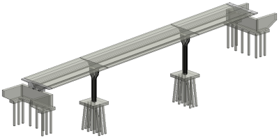
In the following, a simple example of a 3-span beam bridge (as this is more typical than a 1000m+ span suspension bridge, although we all like to show big applications) is given to illustrate this option for doing “BIM in infrastructure” without running into problems as mentioned above.
The Workflow allows generating both models. An optimised one for structural analysis purposes and a highly detailed model for drafting and further documentation.
For non-disruptive data transfer between software applications, it is essential to have two compatible databases. The higher the compatibility between the databases, the smaller the need for either using external files, like IFC format or for doing manual and repetitive adjustments, both being the most significant source of errors, friction and time loss when it comes to the BIM philosophy. The Revit and SOFiSTiK databases show a very high degree of compatibility.
The basic concept for parametric bridge geometry modelling has been made available many years ago using AutoCAD as a base. It is named CABD standing for Computer Aided Bridge Design, and it enhances the modelling and analysis of bridge structures.
The bridge model is based and relative to primary and secondary axes. All axes are defined by straight parts, curves, spirals and parabolas for plan and elevation. All locations along the axes are referred to as stations, which are used for various “points of interest” (called “placements”) such as support positions, cross-section changes, construction joints, cable connection points.
Variable dimensions of cross-sections also refer to the available axes. One can define formulas, functions and variables by linking the “station along the axes” with a value and interpolate cross section between the stations. Typical variables can be such as cross fall, cross-section height, web thickness, roadway width, effective width. These variables are linked to the corresponding dimension of the primary cross section shape, and as the model meshes into a structural FE (Finite Element) model, all intermediate sections are derived and interpolated.
This principle applies for all materials and section shapes as well as for all element types (shells, beams, grillages, hybrid models) and also includes the pre-stressing definition if available.
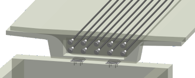
The fact to present tendon geometry in Revit is crucial, as we know of no other tool with this capability. Within the CABD concept all tendon and duct details for both geometry and analysis are defined. We accommodate both the geometrical tendon information in Revit and the detailed analysis and design topics for the structural engineering such as construction stage simulation including time-dependent effects like creep and shrinkage, relaxation.
The SOFiSTiK Infrastructure Extension tool (SiX) allows the user to extract the relevant geometrical information from the SOFiSTiK database and to generate a 3D model into an Autodesk Revit Project. Along with the bridge geometry, several additional objects, like grid lines along the bridge based on the axis alignment and perpendicular grid lines (stations) at the position of placement, are generated simultaneously. Additionally, creating section views can at the position of each placement is possible. All these functionalities are implemented to get most of the information from the database and improve the bridge detailing process in the next design phases.
As previously mentioned the prestressing data, both geometrical and the material is transferred into the Revit file. This functionality of the SiX tool significantly accelerates the modelling and detailing of ducts and tendons, allowing for collisions check (especially in an anchorage zone) and providing relevant information for further documentation such as the list of quantities.
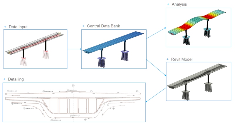
At this stage and by coming back to figure 3, SOFiSTiK workflow for analytical and geometrical modelling, we have now both models available: the geometrical model in Revit and the analytical model in SOFiSTiK.
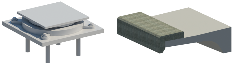
After generation of the superstructure geometry, which often is the most complex element in the bridge design, further objects like bearings, curbs, guardrails, pavement, bearings and other bridge accessories can be placed. New sections and views help the modeller to navigate inside the project and enable the creation of formwork and construction drawings in a convenient way.
Autodesk Revit delivers a wide range of functionalities to generate 3D objects into the model or load previously modelled elements, so-called Revit families. Some of the families may be found in already prepared contents or downloaded as a BIM-object library from a specific manufacturer. The drafter can design own objects and parametrise its dimension and other features.
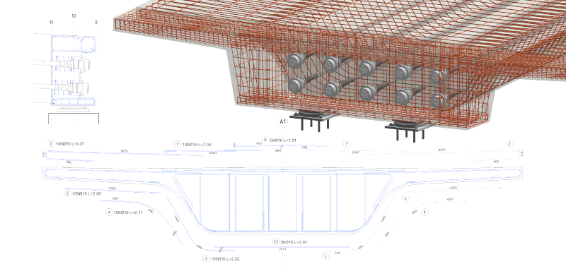
A specific strength within Revit is the possibility to add all the reinforcement, entirely based on the 3D geometry. Within the deck bodies and based on the generated cross sections and logically relative to the outside shape, the reinforcement can be completed with all details.
Autodesk enables other software developers to create add-ons via Application Programming Interface (API) and implements new features. SOFiSTiK Reinforcement Detailing, which offers plenty of useful tools, automates the time-consuming process of sketching rebars and adjusting the dimensions along an axis. Due to the irregular bridge cross-section varying along the curved axis, some of the tools are essential while placing reinforcement in the bridge structure. Drafters can modify rebar sets according to the chosen reference of the reinforced element (Stretch/Trim or Align command) or generate rebars in an element according to the chosen path and host’s constraints (Distribute command).
SOFiSTiK Reinforcement Detailing also offers a wide selection of tools for positioning, annotation and checking of reinforcement. These functionalities significantly accelerate the preparation of 2D drawings and creation of bar bending schedules derived from the 3D model.
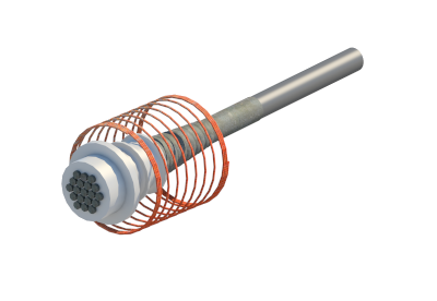
To obtain a higher level of detail (LOD) for drafting purpose, the tendon anchorage object can be introduced. It enables the collision check, which is more likely to occur in the typically highly reinforced anchorage zone.
Using Autodesk Revit as a platform for the BIM Model gives the possibility to enhance a project with additional information, which may not be relevant for structural engineering, but has a significant influence for an overall content.
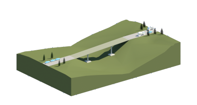
Along with the model visualisation, lists of components and quantities and many other useful tools, Revit offers a definition of topography and coordinates, which can be integrated with other projects and file formats. The model can be seen in a new context, that reflects an impact on the project location and terrain.
One of the basic concepts of BIM Design is teamwork, Revit enables collaborative modelling via cloud or server between users. The workflow can be enhanced by design options and project phases, that increase the coordination and potential of failure detection.
Georg Pircher is an international sales manager and Jakub Bielski is a product manager of BIM infrastructure, at SOFiSTiK AG.
