Design of Infrastructure Projects in Revit
Written by Jakub Bielski, SOFiSTiK AG
This article will cover the topic of infrastructure design from the perspective of BIM technology. It shows workflows and tools provided by SOFiSTiK Bridge + Infrastructure Modeler as an extension to the previously published article Challenges of Bridge Design in Autodesk Revit.
Infrastructure projects consist of different structure types, such as bridges, tunnels, cantilever walls. Engineers and drafters have to face multiple tasks in various design phases and data environments. This article will tackle each of these structure types with a focus on specific tasks.
I strongly recommend you to see the free Autodesk University class Advanced design of Infrastructure Projects in Infraworks and Revit to see more use cases, tools and workflows.
General workflow
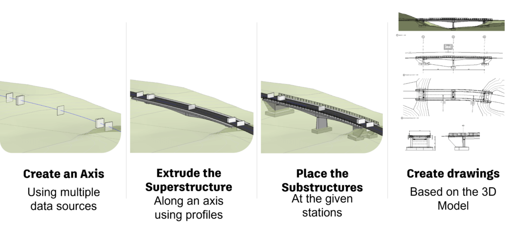
First, let’s briefly look at the general modelling workflow of SOFiSTiK Bridge + Infrastructure Modeler.
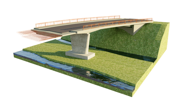
The backbone of the infrastructure project is the axis, which consists of a horizontal and vertical alignment. Axes can also be built by using coordinate points and lines and associated with one another. Later, Superstructure components are created by the profile extrusion along the axis or placement of 3D Substructure components at specific stations. Views, Tables and Sheets are created based on the 3D model.
Structure Parametrization
Infrastructure design features multiple linear structures with complex, quite often complicated cross-sections. User-defined profiles are certainly needed, even by structures with typical shapes. Additionally, varying dimensions along the axis require dedicated tools and solutions to create geometry according to the given constraints (such as obstacles) and project requirements.
SOFiSTiK Bridge + Infrastructure Modeler tackles this task with two different approaches; numerical (using variables and parameters) or geometrical (using points and curves). Also, a combination of these two methods is possible, allowing you to parametrize structure according to the available data and const logical constraints.
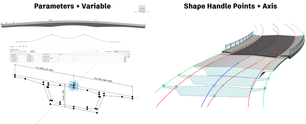
Parameters + Variable
Numerical Parametrization is done by connecting the variable with the Family Parameters (instance). Variable is the representation of the function with defined values at the stations and the transition between them (polygonal or spline). You can create them by using the table (by filling the columns with Station, Value and Transition) or by writing a function in the Equation Editor. Variables are defined in the axis dialogue and can be seen as its integral part. While creating the components, you can assign the variable to the parameter, which will be filled with the values evaluated at the given station.
Points + Axis
The Graphical Parameterization method utilizes Shape Handle Points (adaptive), which control the geometry of the Revit Family (2D Profile or 3D Component). Adjustments of the relative position of Shape Handle Points to the insertion point along the axis changes the geometry of the infrastructure component. It can be used in such a manner that specific points of the cross-section are following selected curves (deck edges following secondary axes) or just a portion of geometry is affected by the shape handle point (only the horizontal position is considered).
Cross Member Array
One of the recent developments of SOFiSTiK Bridge + Infrastructure Modeler was the introduction of Cross Member Array, which, as the name indicates, enables you to place multiple 3D Families along an axis. The significant difference between the Super- or Substructure tools is placing Adaptive Generic Families with multiple adaptive points. These are placed according to the layout rule defined in the tool’s dialogue and control the position and the geometry of the placed components.
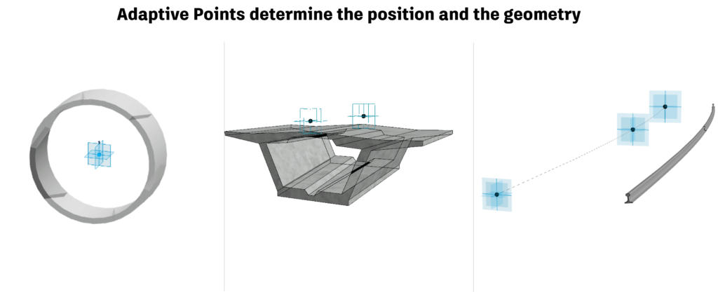
1 Adaptive Point
Controls the position (station/chainage) of placed components. The Variables are evaluated on the same station, and Shape Handle Points are placed accordingly.
2 Adaptive Points
Control the position and the geometry of the component. For proper parametrization purposes, the Local Station was introduced. You can define the station (position) between the first and second adaptive point to define the station for evaluation of variable or position of Shape Handle Point.
3 Adaptive Points
Controls the position and geometry of components with the consideration of axis curvature. Definition of components with 3 Adaptive Points enable to create curved structures. The parametrization is also made with the indication of local stations.
Using Family Parameters or Shape Handle Points, you can parametrize the structure with Variables or other axes similar to the Parameterization of profiles. In case the 3D component has two or three adaptive points, it’s necessary to define the local station between the start and end of the component at which the variable or shape handle point will be evaluated.
Quantification
BIM Models don’t solely represent geometry, they also contain other important data that can be used for multiple purposes. While working in a BIM environment, we can enter, calculate, extract, and share information with other project stakeholders.
One example is the extraction of geometrical data from the model for survey take-off and quantification. We can use the model to read linear, areal, and volumetric values of created components to present them in schedules, quantity tables or export to other scheduling software. You can do it by assigning shared parameters to selected geometrical elements (points, lines, faces, volumes).
Due to the different nature of linear- and 3D components, we can recognize two slightly different workflows.
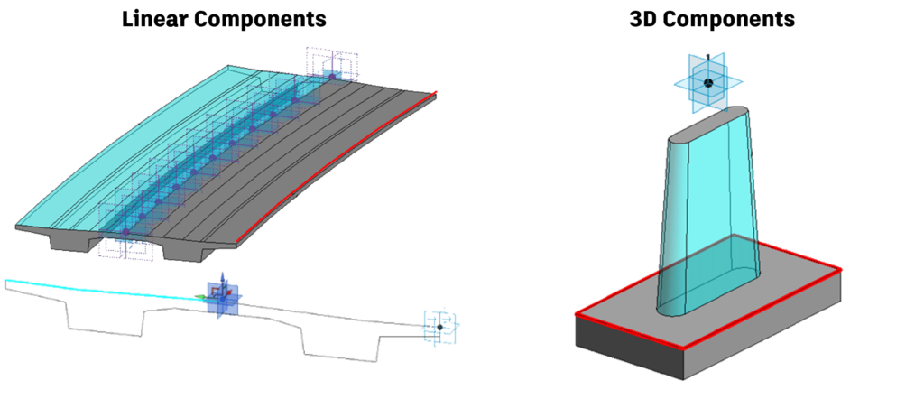
Linear Structures
Linear structures are created by the extrusion of profiles along an axis. Therefore, the definition of the quantities and parameters is also done in the profile family.
- Points to Edges
To get the information of a particular line/edge, we need to select a point extruded along an axis. In this case, we go from 0D to 1D.
- Lines to Faces
To get the information of a particular area/face, we need to select the profile’s line extruded along an axis. If the line does not take part in creating the component, it can be marked as invisible. The value of the area that this invisible line creates will be connected with the parameter anyway. This is useful when you want to calculate the area of not modelled components, such as isolation.
3D Components
- Edges, Faces, Volumes
When dealing with 3D families, the workflow is a little more straightforward. In this case, we can select edges, faces and volumes and assign them directly to the corresponding parameters with the proper type (length, area, volume). This procedure can be done in the Family or the project space.
After connecting the parameters with the geometrical instances, corresponding values will be presented as integral attributes of the model object. You can collect this data for quantity surveys in Revit Schedules or export it to other software for estimation purposes.
