Challenges of Bridge Design and Detailing in Autodesk Revit
Written by Jakub Bielski, SOFiSTiK AG
This article will cover the topic of bridge modelling, detailing, and analysis in Autodesk Revit by using basic functionalities of the SOFiSTiK Bridge + Infrastructure Modeler.
Governments of many European countries encourage engineering companies to advance technological development and move infrastructure projects to BIM technology. There are currently many tools designed with respect to the BIM concept for buildings, but very few for infrastructure projects. As this branch is still under development, consultancy offices or larger companies are trying to close the gap with tools such as Dynamo or other workflows. This situation provides a field for growth for other software providers, which can deliver out of box solutions to tackle specific tasks by taking a different approach.
Building vs. Bridge Design
First, let’s break down the design features of building and infrastructure design.
Yes, the outcome of the project is a structure that provides some function. However, the nature, documentation and description of the structure differ significantly.
We can list some most obvious (as well as significant) ones:
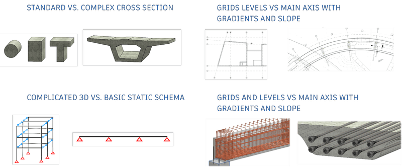
- Cross Sections:
Buildings consist of multiple elements with relatively straightforward cross-sections and geometries. Infrastructure elements (particularly bridges) come with complex cross-sections, often variable and consisting of numerous materials. - Structure Layout:
Buildings are described using levels and mostly perpendicular grids. It can be done in 2D or 3D, but the principle is the same. Infrastructure projects are defined using an alignment and cross-sections at given stations. It allows engineers and constructors to orient themselves according to the curved axis. - Static Schema
Structural analysis of a building requires an FEA model with multiple elements, which create a 3D representation. In the case of bridges, the static schema is relatively simple, but copes with complicated cross-sections, constraints and many load cases. - Structural characteristics
The most common construction material for the building industry is reinforced concrete, whereas the bridge design also accommodates prestressing, steel, and composite structures.
SOFiSTiK Bridge + Infrastructure Modeler
Considering these points, we can conclude that simply adjusting the building workflows and tools for infrastructure purposes are not enough. There might be too many bottlenecks and conceptual problems. Therefore, it makes sense to take a blank piece of paper and tackle these issues one by one.
SOFiSTiK Bridge + Infrastructure Modeler for Revit is an application based on the Revit platform dedicated to Infrastructure design in a BIM environment.
Additionally, some more design requirements were put in front to provide the best possible experience while modelling.
The workflow needs to be:
- Intuitive – Easy to use interface, logical modelling steps throughout the project.
- Dynamic – Generation and modification in real-time according to given data, ability to change an input at any time
- Generic – Engineer decides what and how he wants to model, no black boxes or wizards
- Fit into current workflows – Help change the industry, not force it
Modelling
Let’s look into the aspect of modelling bridges.
+ Coordinates
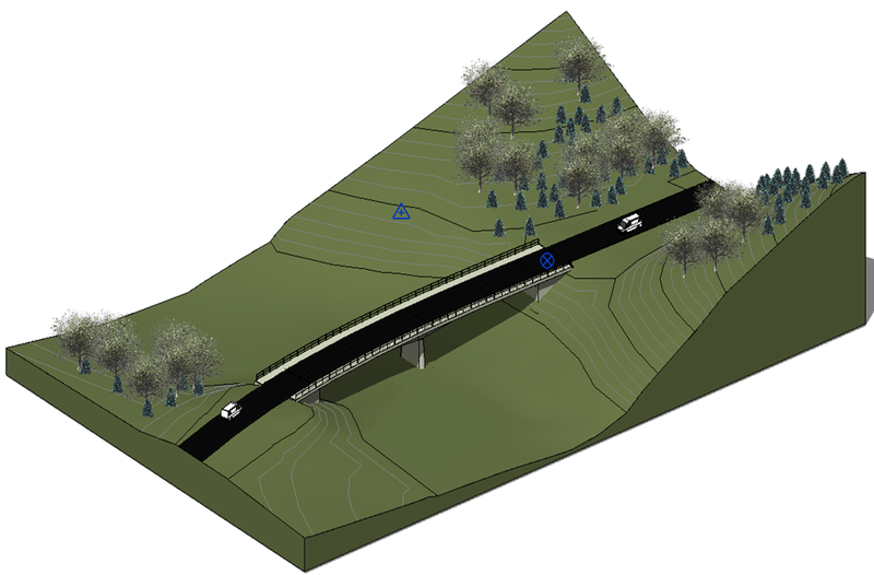
One of the great advantages of designing 3D models and Revit is the possibility of creating a structure according to real-world coordinates. Using this data, we can connect different models, annotate them and coordinate multiple disciplines at once.
Bridge design is no exception. Although we will dive into the axis properties later in this article, created components represent real objects with their dimensions, positions and features related to geo-referencing.
Therefore, it’s important (although not essential) to take care of coordinates before we start modelling. Project base point, Survey Point and Internal origin represent three different coordinate systems with different roles. You can create some elements, e.g. axis, with reference to these three coordinate systems.
Remember that any created element will behave as a Revit object and, therefore, be influenced by its changes.
If you need some more information, you can look at Autodesk Knowledge Network to find out more.
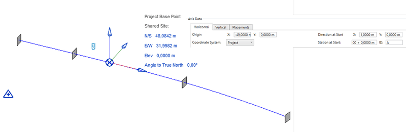
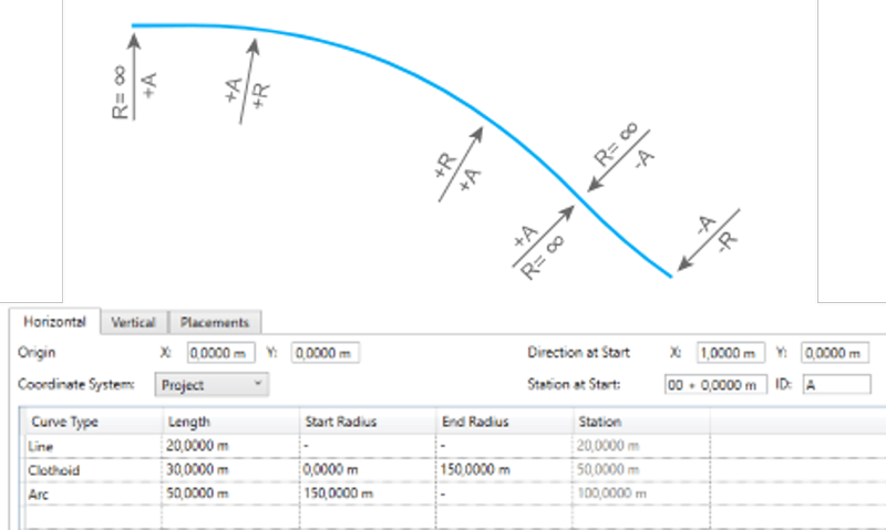
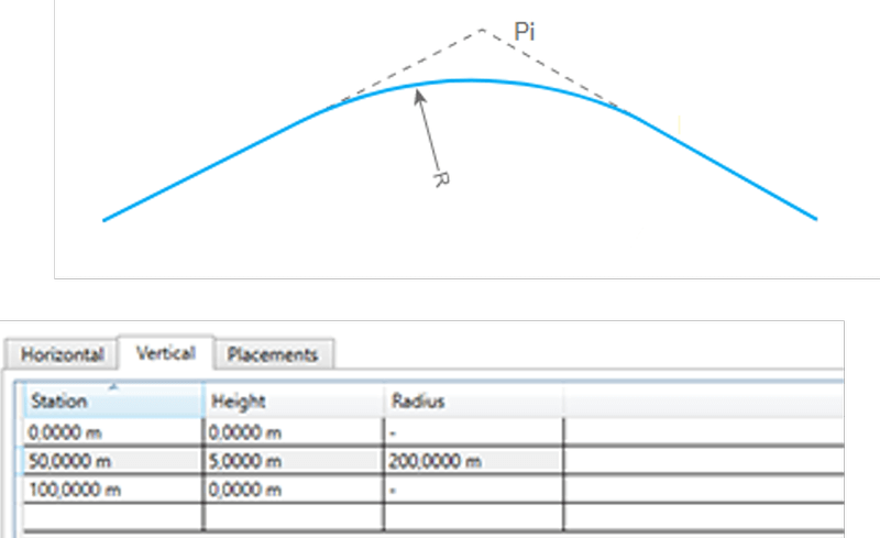
+ Axis
Let’s start modelling! As mentioned before, we need an axis to describe the infrastructure elements adequately. An axis, the backbone of the model, is used to connect various elements. Mostly it’s a 3D curve described with horizontal and vertical alignment parameters. These two curvatures are combined to create a double curved line. Connecting point coordinates or multiple curves can also achieve it. It depends on what kind of input information is available.
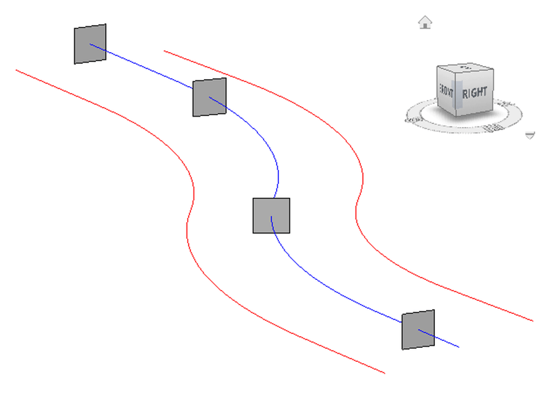
An axis can also contain other information such as placement, variables and secondary axes.
Placement (grey squares), or so-called point of interest, is a point at the axis to indicate a specific station. Mostly where significant change occurs, e.g. start/end of linear component, substructure, additional elements.
Secondary axes (red lines) are lines created based on the main axis with an offset. They inherit geometry and stationing and can be used in the creation and parameterization of elements.
+ Superstructure
The superstructure component is a linear structure created on the axis between two placements.
Its geometry is defined by profiles (placed along an axis) connected to form a 3D component. Due to their nature, these elements are complex in shape and may consist of multiple profiles and double-curved faces.
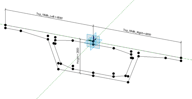
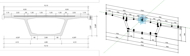
As shown in the picture below, superstructure components may have varying dimensions. Therefore, Bridge profiles need to be correctly parametrized to accommodate these changes and produce an accurate 3D form.
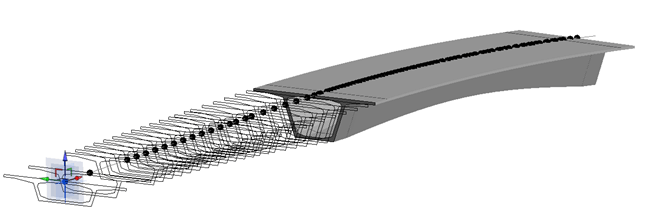
This task can be achieved by defining variables. Variables are formulas that describe a change of specific values along an axis.
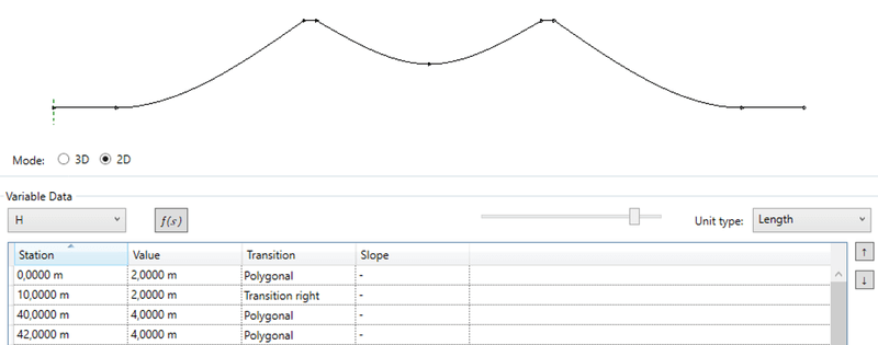
You can see how the geometry of the variable resembles the geometry of the superstructure component.
+ Substructure
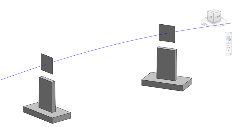
Other types of components are called substructures. These elements are placed at specific placement (station) as parameterized 3D generic objects. Due to its nature, it’s far easier to define whole components using the Revit Family functionalities and utilize SOFiSTiK Bridge + Infrastructure Modeler to place them at a specific station and orient to the axis or given angle.
+ Bridge Equipment
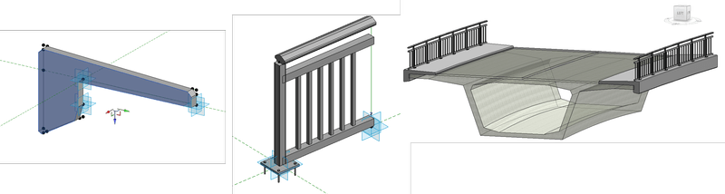
Infrastructure projects consist of many different elements for utility and safety purposes. Regarding bridge design, two of the most common ones are curbs and railings (or barriers). These elements are created with respect to the defined superstructure geometry, e.g. decks superelevation. And we can model them in such as well. Using different generic families and dedicated tools, you can extrude curbs (or parapets) along the given edge or place chainage of railing panels with respect to the curvature, superelevation and additional offset parameters.
Drawings
+ Section Views
A new approach to infrastructure modelling also indicates detailing. We cannot do the same as previously and expect different results. Creating a section view in Revit can be a child’s play as long as everything is perpendicular or parallel. We know already that it’s not the case in infra projects. Using Revit native tools, it can be difficult to precisely calculate the position of a given station and tangent to the axis (especially for spiral curves). Therefore, we can use existing axis information to place and orient the section perpendicularly to ensure a perpendicular alignment. Additionally, we can reach out for Profile information and generate annotations automatically.
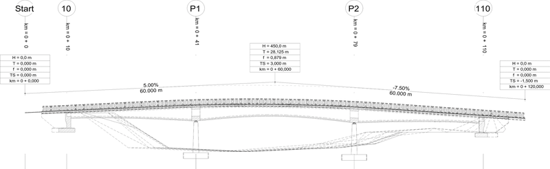
+ Longitudinal View
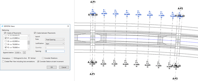
Developed, unfolded, longitudinal view. Or commonly called profile view is a special kind of section that is not created along the straight line. It rather cuts the structure along an axis to show the positioning, dimensions and elevations of placed elements. This feature is not available in the Revit platform yet (till version 2022.1 at least), so we needed to create our section to represent all related elements intersected by or projected on the cutting plane. As a result, we get a section view with detailed elements created based on the 3D model. We can also place some additional detail with descriptions of placements and vertical alignment.
You can find further information in the Autodesk University 2018 class Challenges of Bridge Design and Detailing in Revit and the SOFiSTiK Bridge + Infrastructure Modeler product page.
Read also the article on Design of Infrastructure Projects in Revit!
