Automatic Mesh Generation – The Principles
In this post, I’d like to explain the principles of the automatic meshing in SOFiSTiK. But before we look into the meshing itself, let’s touch on what are finite elements.
The basic concept of finite elements is that the big unsolved problem – in our case, the structure – gets divided into several smaller ones. Every one of these pieces represents a set of element equations to the original problem. All those sets of element equations get systematically recombined into a global system of equations for the final calculation.
The main takeaway; you just break down a big problem into several simpler to solve problems.
With that out of the way, let’s look into the meshing process itself.
When sticking to the graphical workflow to build the structural model, it is not obvious what happens when hitting the export button. And in most cases, it might not be necessary to look under the hood at all.
However, today, we will do precisely that. We will look into the automatic mesh generation process.
When creating a model in “SOFiPLUS” (AutoCAD), the Revit plugin “Analysis and Design” or the McNeel Rhinoceros interface you are not working with finite elements; you actually work with structural elements.
What are Structural Elements?
Structural elements represent members of the structure such as beams, columns, slabs, walls, single supports and more.
They include relevant geometry and structural information, which is essential to describe the calculation model and to perform the analysis and the design at a later stage.
There are four essential structural elements:
Structural Points
Are defined at a specific position in the model and may represent a support condition, a columns head or punching information.
Structural Lines
Can include information about support conditions and cross-sections. Sometimes also used to influence the meshing behaviour as a lose geometric curve (no cross-section information or support conditions).
Structural Areas
Are defined by a closed set of inner and outer boundary curves and may have a geometric surface description assigned to it. Typical properties are thickness and element formulation.
Structural Volumes
Are defined by a set of enclosing structural regions. They can be meshed either unstructured with tetrahedral elements or structured by extrusion or rotation with hexahedral elements.
The Mesh Generation in SOFiMSH-C
Let me walk you through the mesh generation process and explain what happens behind the curtains.
First of all, and you might guess it already, to generate a mesh, there have to be structural elements. When you hit the export button, SOFiMSH-C, which is the program module to generate the finite elements, starts doing its magic.
SOFiMSH-C analyses and processes the entered information of the structural elements and describes them. Structural lines are defined by their endpoints, structural areas by a closed sequence of structural edges.
Now, as the structural elements are described, it is time to create the actual finite elements, preferable quadrilateral elements.
First of all, a triangular mesh is generated for the entire model.
Those triangles represent the basis for building the quadrilateral mesh.

To get the requested quadrilateral mesh, triangular elements in pairs (T1+T2) get combined.
The pairing process includes checking and prioritising, which impacts the sequence of creating the quadrilateral elements—quality assurance for the final mesh, so to say.
The process from triangular to quadrilateral elements is not a simple merge. Two triangular elements get replaced by four new quadrilateral elements. You can see it in the graphic below.
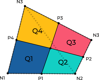
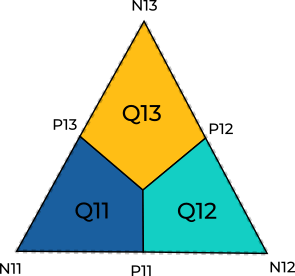
There is a chance that at some spots, triangular elements remain. But there is a smart solution to transfer those into quadrilateral elements too. They get solved by dividing them into three quadrilateral elements.
Now that we get an idea about the process, let’s check it on an example, a square slab.

First, the slab gets divided into triangular elements, the maximum element size, which was allocated based on the structure size or set by yourself, is taken into consideration in this step.

Pairs of triangular elements get replaced by four single quadrilateral elements.

Remaining triangular elements will be resolved by dividing them into three quadrilateral elements.

At the very end of the process, not mentioned yet, a node relaxation takes place. It ensures a high quality of the mesh.

And that’s all about the principles of the meshing process in SOFiSTiK.
Besides the automatic mesher SOFiMSH-C, it is also possible to create a full user-defined mesh. It can be achieved by using the program module SOFiMSH-A in the text interface Teddy.
Now, as you know about the principles of mesh generation in SOFiSTiK, you might see the mesh-related warnings in a different light. And maybe it helps you to fix mesh issues or to interfere with the meshing process in a better way.
