Utilisation Factor of a Reinforced Concrete Beam
The presented workflow shows a possible way to analyse the Utilisation Factor of a Reinforced Beam using SOFiSTiK FEA.
You’ll learn about the steps calculating the utilisation factor of longitudinal reinforcement as well as shear reinforcement based on a given reinforcement in a beam and design load cases.
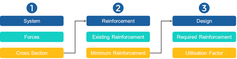
There are three main sections in this workflow to get the utilisation factor along with a beam:
- setting up an analytical SYSTEM, loads and design combinations
- evaluating the existing REINFORCEMENT
- performing the DESIGN to calculate the utilisation factor
To jump ahead to a specific step, use the following links:
Step 1. The System
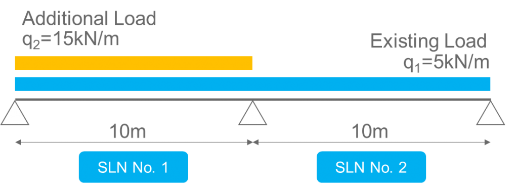
To describe the workflow a simply two-span system is used in SOFiPLUS. For each of the spans, a separate structural line was created. Besides the dead-load case, two more load cases are assigned. Latter represent the existing variable load q1 (which was used to design the beam in the first place) as well as q2 (additional load) which shall be used for the assessment.
Besides the geometry, the definition of the existing cross-section is a significant part. If you’re lucky, you’ll get the dimensions and information about the existing reinforcement from well-drawn drawings. If not, quite a lot of research needs to be done to really understand what amount of reinforcement was used for the beam in the first place. The information is necessary to properly define the cross-section in SOFiPLUS “Cross Section Editor”. Or by using the module AQUA in CADiNP as an alternative. In the following the “Cross Section Editor” is used.
You need three commands in the “Cross Sections Editor”.
- Define Boundary
- Shear Cut
- Single Reinforcement.
If the cross section isn’t that simple as a rectangle or comes with a more complex reinforcement layout, it may be necessary to consider other commands too.
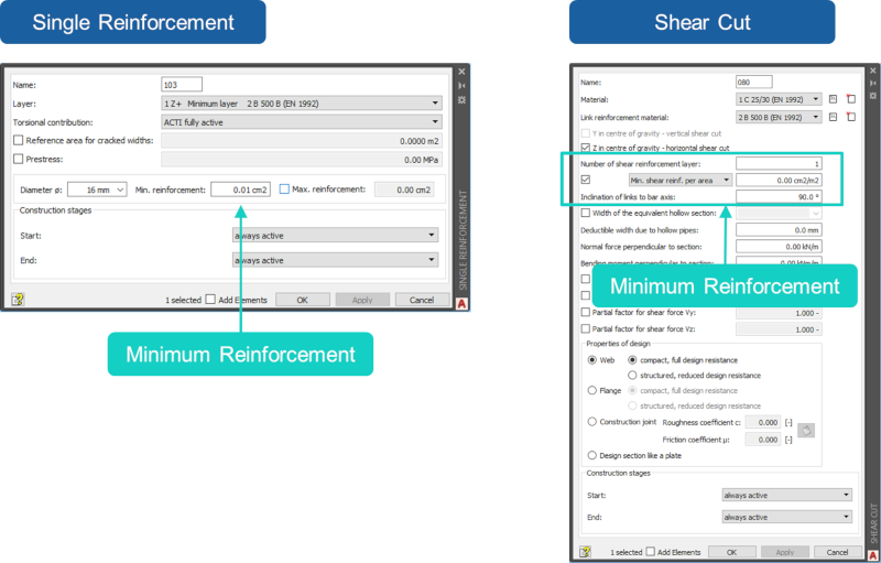
Essential in this step, placing the reinforcement within the cross-section as shown in the as-built drawings and assigning a minimum reinforcement amount of 0.01 cm² for the longitudinal and 0.01cm²/m for the shear reinforcement (Within shear cut – don’t forget to tick the checkbox). No need to enter the existing reinforcement yet. However, separate the reinforcement layer properly in lower, upper or side rebar layer so you can identify them afterwards easily. The information is needed in the next step when assigning the actual reinforcement values within AQB.
Step 2. The Existing Reinforcement
The system geometry, the cross-section including the correct location of the reinforcement layer as well as the necessary information of reinforcement values are available. So let’s focus on the fine-tuning of the existing reinforcement. This will be done by using the reinforcement layer information of the cross-section within the program module AQB (cross-section design). Three longitudinal layers (top, bottom and side) and the shear reinforcement layer are used. To make the workflow a bit more interesting let’s assign different shear reinforcement values depending on the position of the beam (structural line).
You’ll need CADiNP to do the next steps. No worries if you haven’t used the text input CADiNP before as the input is straightforward.
Within “AQB” the command “BEAM” modifies the reinforcement in beam elements. There are 4 required inputs.
- Select the structural line
- Define the allocated part
- Switch the input method to reinforcement
- Assign reinforcement value to different layers
The command “BEAM” is followed by the command “REIN” to finally save the reinforcement as a design case.
Let’s check the input for the longitudinal and shear reinforcement to define the existing reinforcement in the beam.
Define the existing reinforcement amount of the longitudinal reinforcement
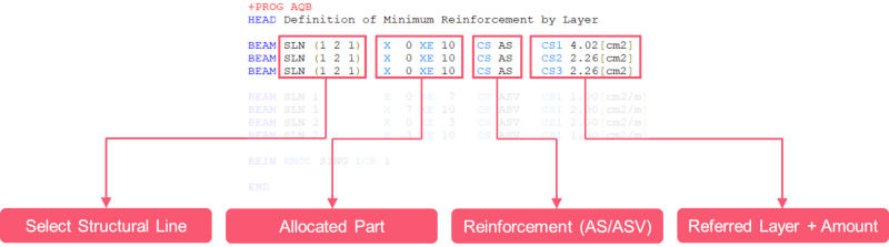
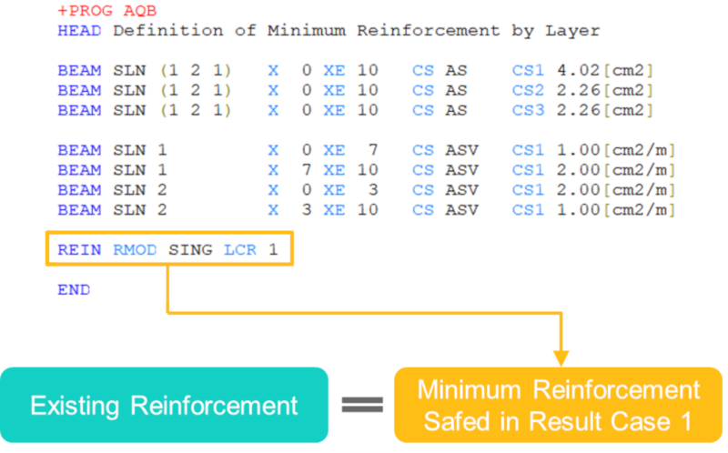
Start with selecting the structural line numbers. The shown input “SLN (1 2 1)” means- translated in human language – to pick structural lines (SLN) with number 1 and 2. The input “(1 2 1)” is a way to select a list of elements with an indicated increment of 1 – the increment is the last number within the brackets.
Followed by the input of the range along the beam the x-position is defined by “X 0” (Start) and “XE 10” (End) what completes the relevant input for the geometry.
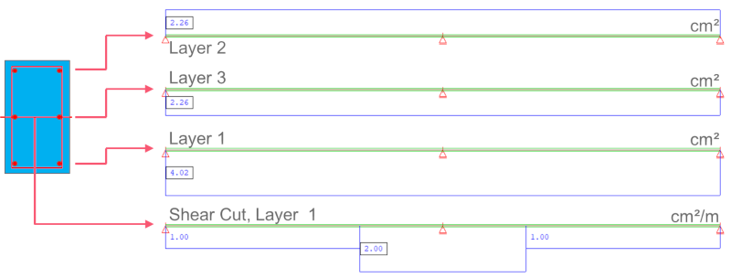
The input “CS AS” is used to switch from a construction stage input method to the longitudinal reinforcement input. At the items “CS1”, “CS2”, “CS3”, “CS4” the reinforcement values can be entered in regards to the reinforcement layer defined in step 1. “CS1” 4.02[cm2] will assign a reinforcement value of 4.02[cm2] to Reinforcement layer 1.
Define the existing reinforcement amount of the shear reinforcement
The items used within the “BEAM” command to define the shear reinforcement are like those defining the longitudinal reinforcement. Only the item values are slightly different.
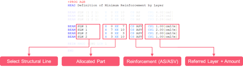
As mentioned earlier the definition of the shear reinforcement shouldn’t be assigned constant along the structural line. Instead, different reinforcement values are used. Therefore, the structural lines are selected separately.
The input “SLN 1” selects the structural line number 1 only. From the x position 0[m] to 7[m] a shear reinforcement value of 1.00[cm2/m] is used at item “CS1”. “CS ASV” switches to shear reinforcement input method for the input at “CS1”.
Save the longitudinal and shear reinforcement information in a design result case
To store the longitudinal and shear reinforcement information as design result case – the input line “REIN RMOD SING LCR 1” is used. The item “RMOD” with value “SING” triggers a single calculation of the reinforcement and saves the entered reinforcement as minimum reinforcement along the beam in design result case “LCR 1”.
Before jumping to step 3 – check the saved reinforcement in
Step 3. The Utilisation Factor
The final step is to get the utilisation factor along the beam. Therefore, add a new AQB module to perform the design of the beam elements considering the additional loads.
The following input lines perform a standard design with two exceptions
- A specific minimum reinforcement design result case (1) is used (from step 2 in this workflow).
- Any increase of the reinforcement during the design process needs to be suppressed.
Use a specific design result case as minimum reinforcement as initial reinforcement
Using a specific design result case as initial reinforcement is done by the input line “REIN MOD SECT RMOD ACCU LCR 1”. “RMOD ACCU” initiates to use the existing reinforcement in design result case 1 “LCR 1” as minimum reinforcement.
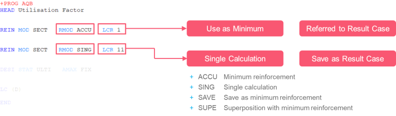
As finally, a design needs to be performed – another input line is required to save the design results. “REIN MOD SECT RMOD SING LCR 11” performs a single calculation and saves the design results in case 11.
Suppress reinforcement increase
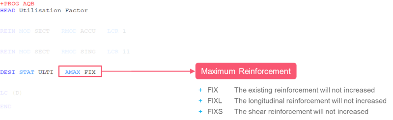
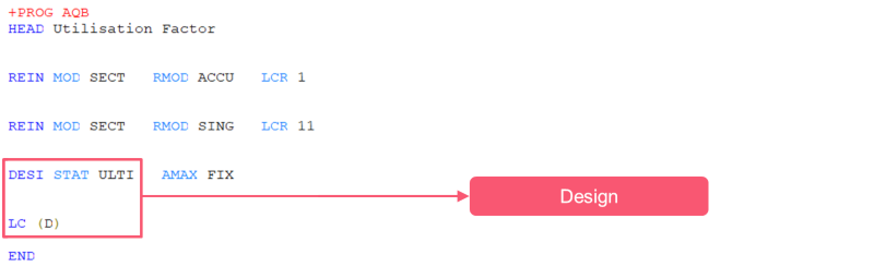
This is the most critical part of the input in this AQB module. At the end of the input line “DESI STAT ULTI AMAX FIX” you’ll find “AMAX FIX” which freezes the selected minimum reinforcement information during the design. No increase of the reinforcement happens.
To get the utilisation factor based on the frozen reinforcement and the design load cases the input “DESI STAT ULTI” as well as LC (D) is required. The input LC (D) will consider all design load cases saved in the database for the design. To use a specific load case such as 2129 – if you want to consider the maximum bending moments in MY direction only – replace (D) to LC 2129.
Utilisation Factor
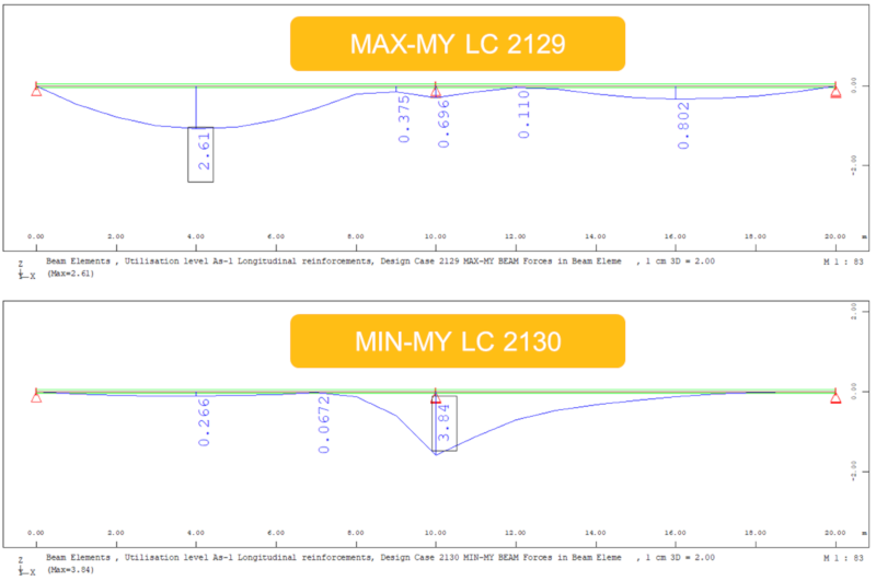
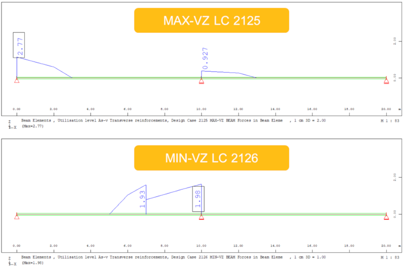
To check the utilisation factor graphically along the beam use WINGRAF. For each of the considered design load cases, WINGRAF represents a utilisation factor.
Open WINGRAF and go straight to the sidebar. Expand “Design” – “Utilisation Level” and select either “As-l Longitudinal Reinforcement” or “As-v Transverse reinforcement” as well as one of the considered design load cases to visualise the utilisation factor.
Wrap-up
Three steps are required to get the utilisation factor along the reinforced beam for longitudinal and shear reinforcement.
Besides setting up the project in SOFiSTiK Structural Desktop and the graphical definition of the cross-section in SOFiPLUS – CADiNP is part of the workflow. The CADiNP section can simply be copied and reused in other projects. To present the utilisation factor
Software version: SOFiSTiK FEA v2018-06.
