Compression-Only Bedding and Uplift Effect
The best way to explain the workflow of compression-only bedding for structural areas is by showing it in a simple example.
To get a compression-only effect, non-linear analysis of your system becomes necessary.
Modell – Example
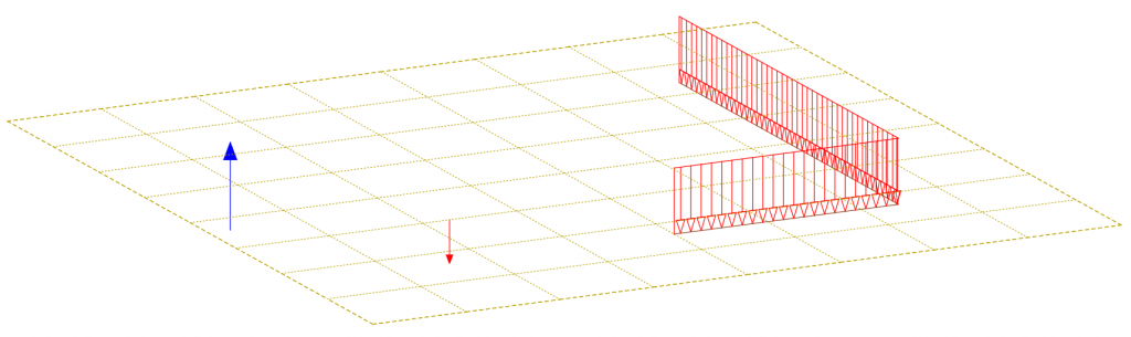
Structural area 10x10m with a thickness of 200mm. Not realistic, but it’ll dramatise the uplifting effect later. Two line loads and one single load won’t cause an uplifting, so another load pointing upwards is added in the opposite corner.
Bedding Material – Definition
To generate the effect of compression-only bedding for structural areas, you’ll need to define a bedding material assigned to the structural area element.
Create a new material or clone the material you want to use for the structural area and rename it to make it clear the material comes with bedding properties.
Within the material dialogue box, you’ll find three tabs “Properties”, “Strength”, and “Bedding”.
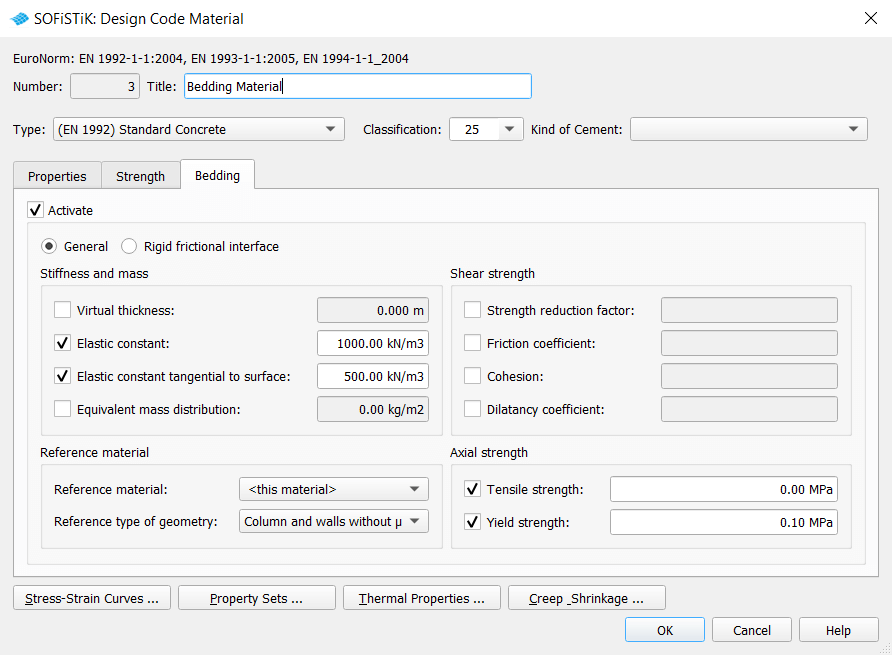
To activate the bedding in the material, check the box “Activate” in the top left corner within the “Bedding” tab.
The relevant input to achieve a tension or compression-only bedding in the non-linear analysis can be found in the sections “Stiffness and mass” and “Axial strength”.
1 Elastic constant
The elastic constant represents the actual stiffness of the bedding.
2 Elastic constant tangential to the surface
The elastic constant tangential to the surface represents, as you might imagine, the stiffness tangential to the surface.
3 Tensile strength
The maximum tensile stress entered value must be defined and activated to get the uplifting effect. Enter the required value; using zero won’t allow tension at all.
4 Yield strength
There is also the possibility of limiting the maximum compression stress of the bedding.
Bedding properties can be applied to every material in your project.
Activate Bedding for the Structural Area
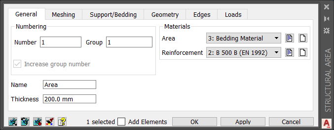
Adding the bedding properties to the material is the first of two steps. Step two needs to activate the bedding for the structural area. Open the “Structural Area” properties by double-clicking on the specific area.
Ensure that the bedding material is assigned to the structural area. Double-check the input in the first tab, “General,” of the “Structural Area” dialogue box.
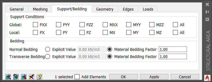
Then switch to the third tab, “Support/Bedding”, and within the section “Bedding”, activate the “Material Bedding Factor”. Depending on your calculation, you switch on the “Normal Bedding” and/or “Transverse Bedding”.
This step is very important; otherwise, the bedding information you entered within the material won’t be considered.
The default factor is 0.00. Change the input to 1.00 to take 100% of the entered bedding values into account.
Now, as the model is complete, let’s focus on the required input for the non-linear analysis.
To get compression-only effects, a non-linear analysis is required. It can be done entirely within “SOFiSTiK Structural Desktop” using the tasks “Combine Loads” and “Analysis of Combined Load cases”.
When performing a non-linear analysis, it becomes necessary to use manual combined load combinations over the superpositions. The superposition concept isn’t valid anymore.
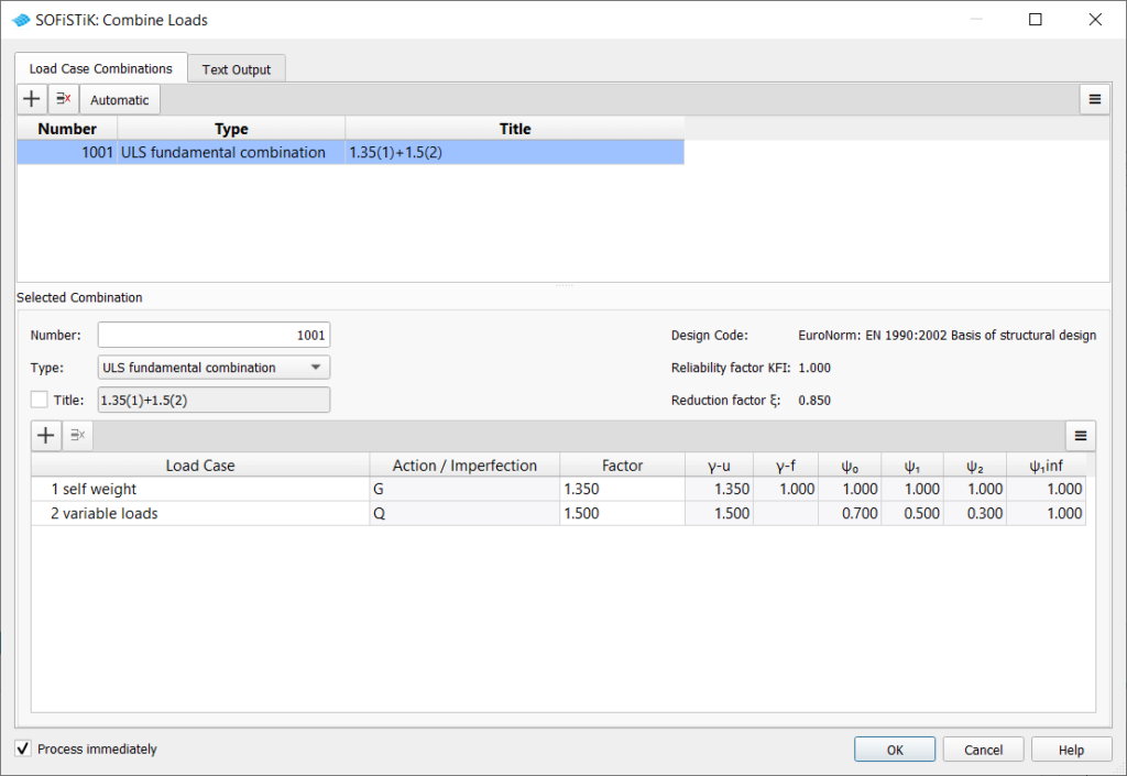
Combine Load Cases
- Add a new combination.
- Select the result type of the combination you’re going to create.
- Then create a new combination with the “Plus” button above the below table.
- Tweak the combination factors as you want or keep the code default.
Proceed with further load cases or combinations as you need for your project.
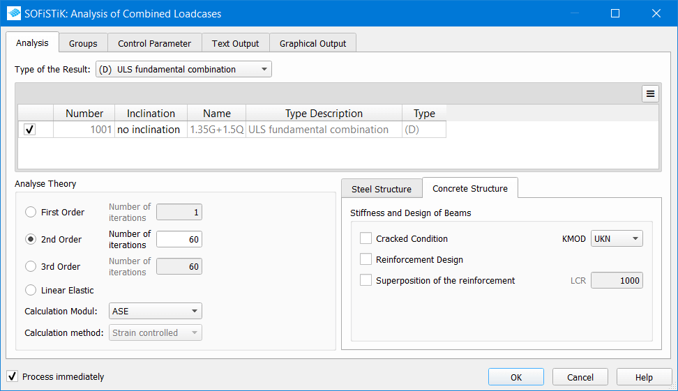
Analysis of Combined Load cases
The load combinations are available for the non-linear analysis now. And can be calculated with the “Analysis of Combined Load cases” task.
Within the tab, “Analysis”, ensure the combination you want to calculate is activated – tick the checkbox to the left of the load case number. If you used different result types in the “Combine Loads” task, you might need to select the correct one in the dropdown menu above the table.
In the “Analysis Theory” section, choose the option “2nd Order”. The number of iterations is set to 60 by default. If you don’t get equilibrium during the calculation due to insufficient iterations – increase the number. If the equilibrium wasn’t achieved for a different reason, check the residual forces in WINGRAF.
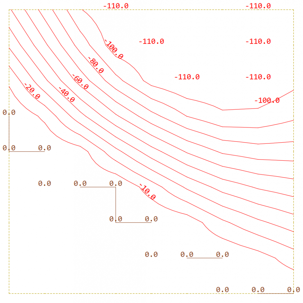
Results
The maximum tensile stress of 0.0 MPa was entered in the material bedding information – the lower-left corner shows 0.0 kN/m². No tensile stress at all. The opposite corner shows the defined maximum stress of 110 kN/m² (0.110 MPa). The maximum compression stress stays exactly below the defined limit.
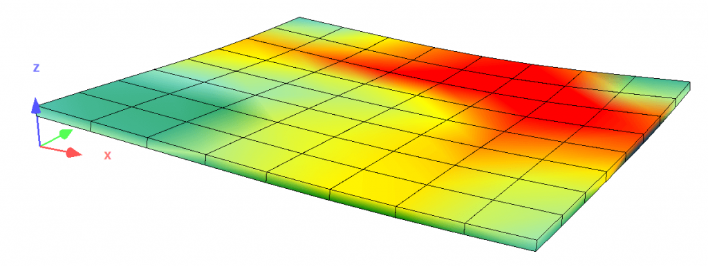
The uplifting can also be viewed within the “System Visualisation. Check the difference between the coordinate system origin and the structure itself.
Download the “Compression-Only Bedding of Area Elements” example. v2018
Download the “Compression-Only Bedding of Area Elements” example. v2020
Download the “Compression-Only Bedding of Area Elements” example. v2023
Download the “Steel Connection Compression-Only Bedding” example. v2020
Download the “Steel Connection Compression-Only Bedding” example. v2023
Wrap-Up
Achieving compression-only bedding for structural areas requires, first of all, a non-linear analysis. Besides that, the bedding properties need to be applied to the material of the structural area. Furthermore, the bedding must be activated in the structural area to consider it in the calculation. Adding bedding properties to the material is a great option for reusing similar settings for different structural areas of a foundation.
Software version: SOFiSTiK FEA v2023-0.
