The Running Imposed Load Command in SOFiPLUS
The “Running Imposed Load” command enables you to distribute one single free load or a group along a curve (straight line, arc, spline and polyline).
A fixed number or a specific step length are available options to create the load positions and cases.
The Reference Load and Path
Before you run the command “Running Imposed Load, ” you must do the following preparations to get smoothly through the entire workflow.
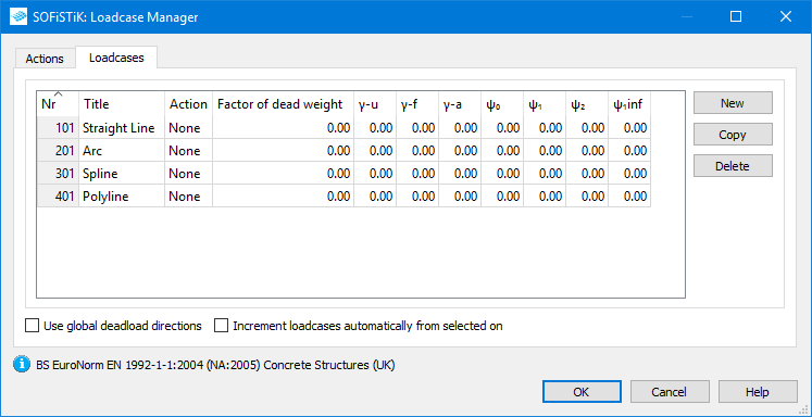
Create a Reference Load Case Number
The reference load cases number of the load cases you will copy along the path. You can create a new load case in the Load Case manager within the load tab in the SOFiPLUS Sidebar.
Keep in mind that this reference load case will be used as base load case number for all duplicated ones. I’ll come back to this later in the workflow. Just keep plenty of spare numbers after the reference load case number.
Create a Reference Free Load
The “Running Imposed Load” command creates duplicates of free loads along a path. Therefore, you need to create the reference load case upfront. It is necessary to use a free load or a group of free loads as reference loads.
Distribution Path
It’s not mandatory to define a path, as you’ll get the option to create one straight in the “Running Imposed Load” command. However, this capability is limited to polygonal lines. I recommend creating a path – if it’s more complicated – beforehand.
Running Imposed Load – The Workflow
As you have a reference load and reference load case number and the path available – let’s focus on the “Running Imposed Load” command.
Creating loads along a path is done by the following 4 steps.
1 Type of Distribution
2 Increment of Target Load Case
3 Select or Create the Path
4 Select the Reference Load
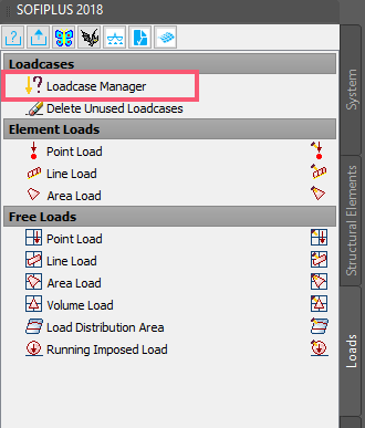
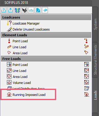
Open the command “Running Imposed Load” in the SOFiPLUS sidebar tab “Loads” to get started.
The “Moving Load” dialogue box comes with a few options only in the first few – but will allow further inputs by the right-click context menu.
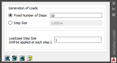
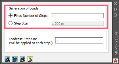
1 Type of Distribution
The uppermost section of the dialogue box allows settings of the specific number or step size to generate the loads along the selected path.
The path can be a straight line, arc, spline or polyline. Before selecting the path, I recommend completing all settings in the “Moving Load” dialogue box.
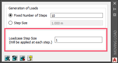
2 Increment of Target Load Case
As a new set of load cases will be generated, it’s required to create a new load case number for every single load position – which is automatically done by the software. However, you get the option to choose the increment between the generated load case numbers. With that said, it’s also essential to understand what’s the reference load case to count from. Well, it’s the load case number that was applied to the load or load group to distribute along the path.
Keep sufficient spare numbers after the reference load case number to avoid clashes with other already occupied ones.
3 Select or Create the Path
You can either create a new path as a polyline by clicking the single points or converting already created elements. Geometries allowed are lines, arcs, splines or polylines.
Use the right-click to open the context menu for further options to select the elements. There is only one command applicable “Pick lines or curves”.
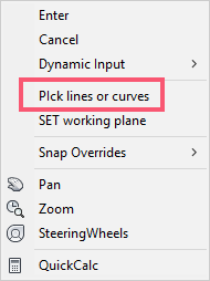
You’ll also find “Pick lines or curves” in the AutoCAD command line.

Confirm the selection with “Enter.”
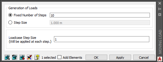
4 Select the Reference Loads
In the last step, you select the reference loads. Combining the different types such as “Point Load”, “Line Load”, and “Area Load” is possible. All loads of a group have to be assigned to the same load case number.

Select all loads to include and confirm with “Enter”.
The command generates the new loads immediately. Checking the new loads is quite easy, and changes can be done immediately. To close the “Running Imposed Load” command, hit the “Esc” or “Enter” key.
Check the new generated load case numbers generated automatically in the “Load Case Manager”. You’ll recognise that every single load position got a separate load case number.
Modify Generated Loads
All new loads are grouped and linked to the reference load or loads. If necessary, to modify the loads, double-click on the created load group (all single load positions). An almost similar dialogue box as while creating the loads in the first place opens. Make the changes and apply them.
Reference Point of The Load Group
Let’s have a look into how the new loads are positioned. The graphic below shows the path (red line), a load group (blue geometries) and the tangent in the reference point on the spline (cyan dashed line).

The reference point for the load group lies exactly at the start of the path. I placed the single load precisely to that location. It’s not mandatory to place a load on that position; it’s just for representation purposes. When the load gets distributed along the path, the tangent information is used to align the entire load group. The load group works like a rigid body that rotates dependent on a tangent on the spline of the reference point.
Watch the Video
Check out the video to see the command in action.
Wrap-Up
The “Running Imposed Load” command is a time-saver to distribute loads along a path. If you aren’t familiar with the text input CADiNP, you might prefer this option too. Benefits such as the flexibility to change the reference load group and adding or removing load positions afterwards are worth looking into that tool.
Download the “Running Imposed Load” example file.
Software version: SOFiSTiK FEA v2018-09.
