The Principles of Parametric Modelling in Autocad and SOFiSTiK
In this post, I would like to introduce you to the principles of parametric modelling in Autocad and SOFiSTiK.
Let’s get straight into it.
Geometric Axis
The concept behind the parametric modelling in Autocad and SOFiSTiK is straightforward. It is mainly built on a geometric axis as a backbone.
The first element we need is the geometric axis or the road alignment.
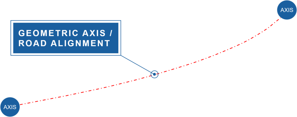
The preferred way to create the geometric axis is using road alignment parameters such as straight lines, arcs or transition curves in the graphical alignment editor. Transferring common AutoCAD elements such as lines, polylines and splines to an axis or even importing alignments from other projects is also possible.
Placements
As the alignment might not precisely represent the bridge length or indicates the start point and endpoint of it – the next step is to specify locations of relevance to the structure.
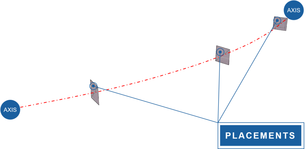
These Placements can represent supports, construction joints or any other essential element of the bridge structure.
Assigning substructure elements to the placements and therefore to the axis is common practice to build a full bridge project in one single model.
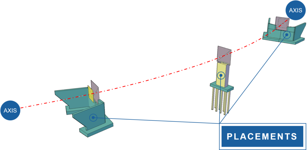
One advantage: the load take-down of the traffic loads to the foundation is precisely considered. Even including a soil-structure interaction is possible.
Cross Section and Variables
Having the axis and the placements set, we can look into the third step – The cross-section definition and variables.
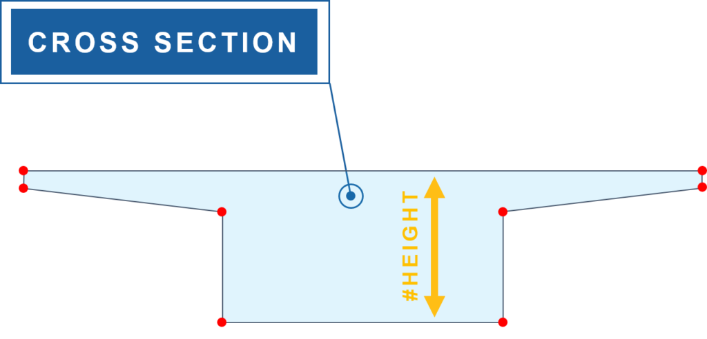
And what would be a bridge without a parametric cross-section, right?
Here is where the SOFiSTiK Cross-Section Editor for AutoCAD comes in. Besides the ability to create any cross-section geometry using common AutoCAD elements, the editor also comes with parametric dependencies.
To learn more about the the parametric options within the Cross-section Editor.
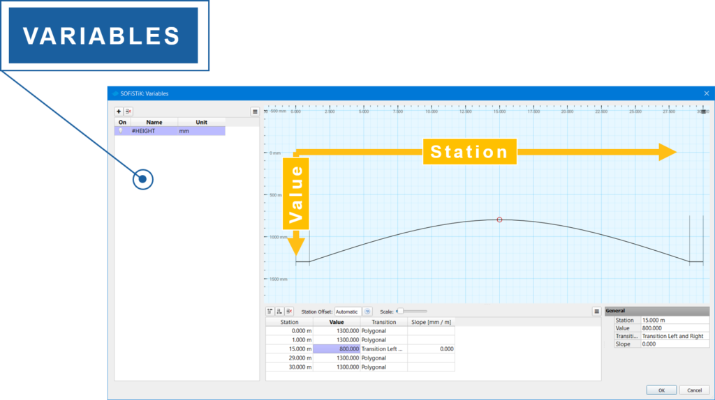
These dependencies can be controlled by variables, which are referenced to the geometric axis and its stations.
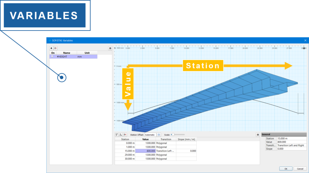
The interaction between the axis and variable drives the cross-section interpolation, which creates the required cross-sections along the axis to get the final model.
Structural Elements
We are only one click away from completing the parametric model.
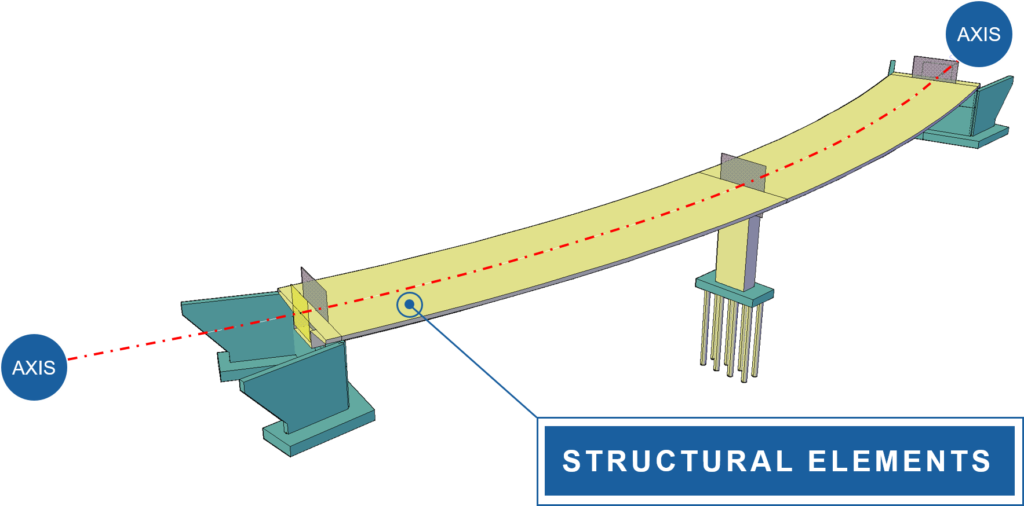
Creating the Structural Elements to the geometric axis is the last step to take. Basically, the cross-section gets attached to the axis. We have now an active link between the axis and the cross-section. And any modification to the axis also applies to the structural element.
This is the last step of parametric modelling of bridge structures with SOFiSTiK in Autocad.
Learn more about the workflow and read the post Basics of Modelling a Parametric Beam Bridge.
Tendons
But often bridges require Post-Tensioning. So how does the tendon creation fits into the parametric modelling?
We learned so far that the geometric axis is the backbone of the entire parametric modelling process. And so it is for the definition of the tendon geometry.
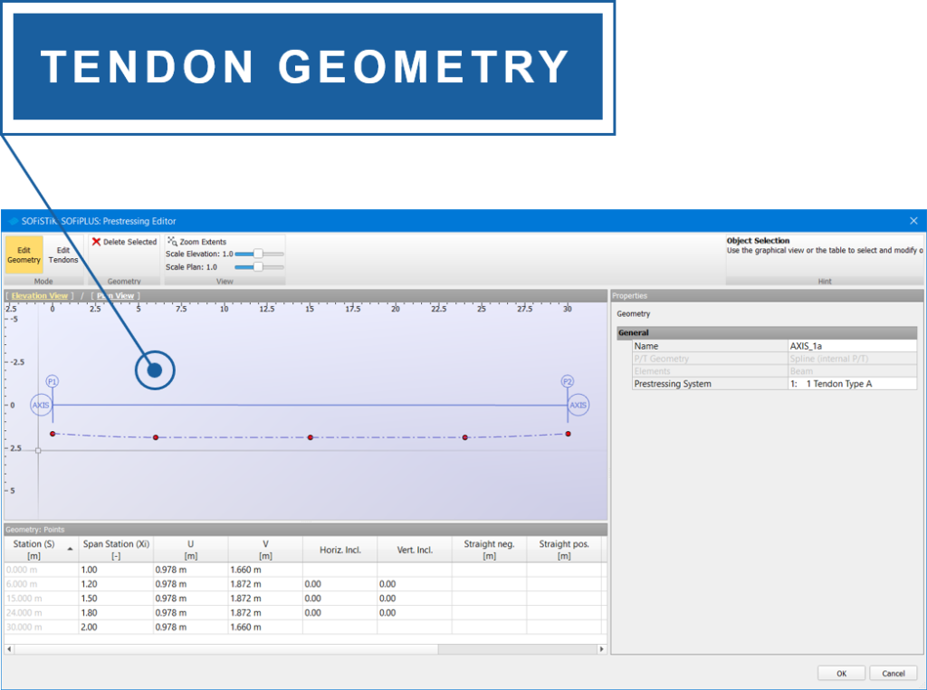
By selecting the geometric axis as a reference, the graphical tendon editor supports you to create and modify tendon profiles.
The Tendon Editor comes with lots of options to define the tendon profile. For instance, you can add and remove control points to the duct geometry. Set properties to the tendons such as jacking procedure, the direction of stressing and construction stages.
After completing the input in the Tendon Editor, the tendon geometry gets generated in your model.
Similar to the structural elements, the tendon geometry is linked to the axis. Any changes to the axis also affect the tendon profile.
Wrap-Up
Let’s wrap things up – the four significant steps of parametric modelling in SOFiSTiK and AutoCAD are:
- To define the geometric axis or road alignment
- To specify placements, which represent the relevant points of the structure along the axis such as supports, start point and endpoint.
- To create the cross-section, which can be either a standard or constant cross-section, or a defined with variables.
- And finally, the creation of the structural elements linked to the axis.
And as for bridges we often deal with post-tensioning,
- Tendon profiles can also be incorporated in the parametric modelling concept.
And most important, any modification on the geometric axis, will affect all elements linked to it.
Software version: SOFiSTiK FEA 2020-4.
