Tendon Geometry – Refer to a Cross-Section Point
Besides the possibility to define tendons referred to a geometric axis, AutoCAD line or drawing it from scratch a third option can be used. Actually, it’s more a combination of a reference on a geometric axis, the parametric input in SOFiPLUS (CABD) and the powerful text interface CADiNP.
In this post, you’ll find a step by step guide from setting up a simple single-span beam to the necessary text input in CADiNP to define the tendon geometry.
Workflow Overview – Reference to a Geometry Point within the Cross-Section
There are some steps to take to complete this workflow, so dividing it into two main parts make sense.
Part 1 – System, Cross-Section Definition and CADiNP Template
Step 1. Create Geometric Axis
Step 2. Create Cross-Section and Geometry Point
Step 3. Assign Cross-Section to Axis
Step 4. Definition of Variables and Values
Step 5. Import of Variables in Cross-Section Editor
Step 6. Definition of Variables within Cross-Section Editor
Step 7. Assign Variable to Vertical Distance
Step 8. Create Tendon CADiNP Template
Part 2 – Required Modifications to the CADiNP Template
Step 9. Additional TENDON Module to Remove All Existing Tendons stored in the Database
Step 10. Definition of the Reference Axis
Step 11. Spans Along the Reference Axis
Step 12. Definition of the Tendon Geometry
Step 13. Constraining Point Along Stations
Step 14. Referring to Cross-Section Point
Step 15. Construction Stages
Step 16. Jacking Information
Step 17. Checking Start and End Point of the Tendon Geometry
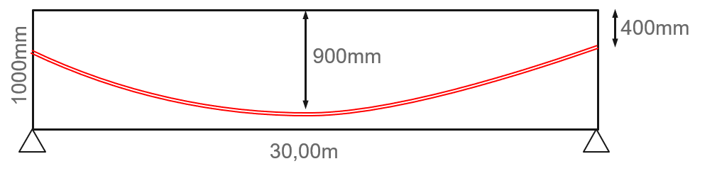
To focus on the relevant things – a single span system and a rectangular cross-section are used to represent the workflow.
System
Cross-Section
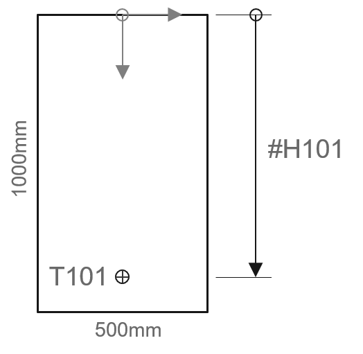
T101 … Geometry Point
#H101 … Variable in
Parametric Information
With the steps and system information in mind, let’s get started with the first step.
You’ll find to each of the steps a short description as well as a video. The videos have no audio track included.
Step 1. Create Geometric Axis
The first step is about to create the geometric axis only.
- Name Axis
- Define Alignment
- Define Placements
Step 2. Create Cross-Section and Geometry Point
Step 2 is about to define the cross-section and assigning the geometry point (T101) within the boundary.
- New Solid Section
- Reinforced Concrete
- Define the Cross-Section Boundary
- Boundary with origin in 0/0
- Point in Area
- Create a Geometry Point
- Use a reasonable geometry point name
- Place geometry point
Step 3. Assign Cross-Section to Axis
Assigning the cross-section to geometry axis is done in step 3.
- Structural Line
- Excentric beam “CS01”
- Select object/segment on axis
- Specify support conditions
Step 4. Definition of Variables and Values
This step is an important one, as it defines the final geometry of the tendons along the axis. You can either skip this part when having already a parametric cross-section and a geometry point within to refer to or as in this example which has a rectangular and constant cross-section define a new geometry point such as T101.
- Geometric Axis
- Variables
- Define a new variable (#H101)
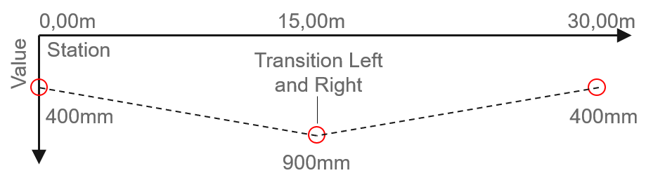
- Enter Values referred to the station or
- copy/paste data from Excel sheet
Step 5. Import of Variables in Cross-Section Editor
The parametric information defined in step 4 needs to be added to the cross-section.
- Cross-Section Properties
- Tab variables
- Import
- Select axis and add a variable (#101) to the cross-section
- Set the default value of the variable
Step 6. Definition of Variables within Cross-Section Editor
An alternative to step 5 is defining the variable within the cross-section properties.
- Cross-Section Properties
- Tab variables
- New variable
- Enter variable name (#H101).
- Set the default value of the variable
Step 7. Assign Variable to vertical Distance
In this step, the defined variable in step 5 and 6 is going to be assigned to the vertical distance between the top of the cross-section and the geometry point T101.
- Parametrics
- Cartesian reference
- Specify constraint point (T101)
- Specify reference point or location forhorizontal distance
- Specify reference point or location forvertical distance
- Assign variable (#H101) to verticaldistance
Step 8. Create the Tendon CADiNP Template
This is the last step of the first major part of the workflow. It’ll show how to generate the CADiNP template file (*.dat) which will be used in the next steps.
SOFiPLUS – Prestressing
- PT Editor
- Assign case and prestressing system
- Nametendon “101”
- Export System.
Ensure the “process immediately” checkbox is deactivated before confirming the export. - Open generated project_bpt.dat from the project directory.
Copy the content to SOFiSTiK Structural Desktop in a new Text Editor (Teddy) Task.
The generated Text file looks as shown below. Depending on the tendons you defined it might have different inputs. However, the general structure is always the same.
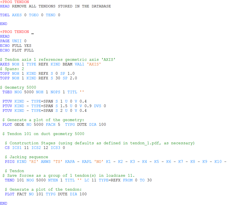
The following steps of the workflow are about the modification of the generated .dat file.
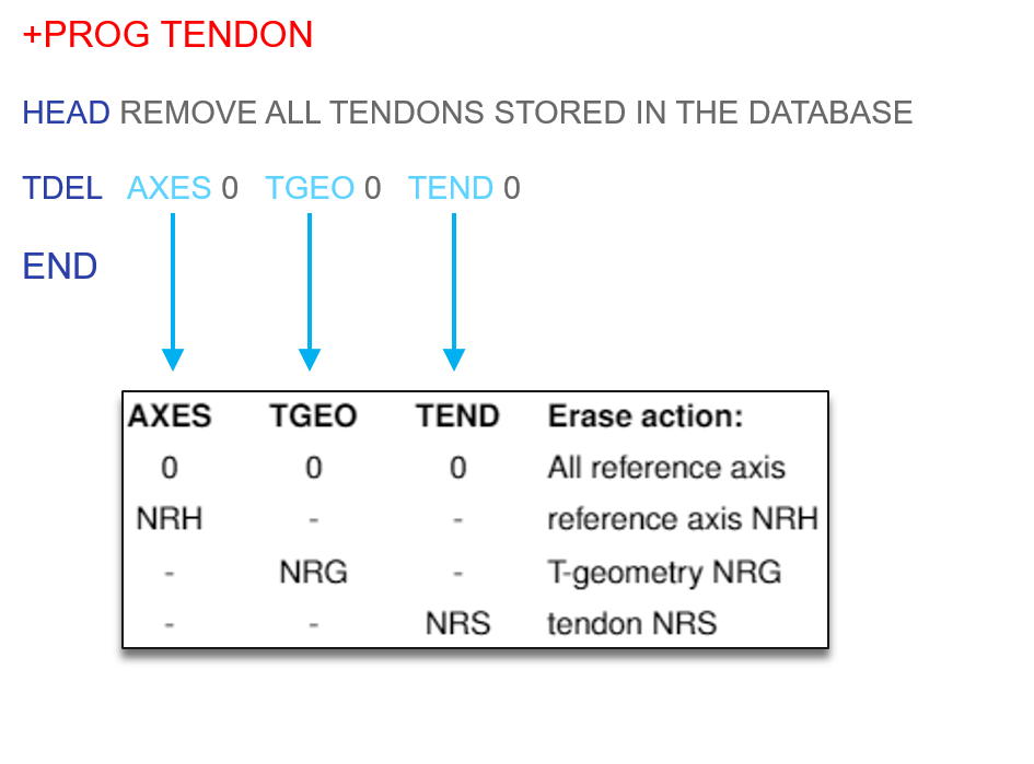
Step 9. Additional TENDON Module to Remove All Existing Tendons in the Database
This step is important and useful when calculating the same tendon module several times for a testing purpose, so overwriting existing information again and again. The added input helps to avoid error messages due to already existing tendons.
Step 10. Definition of the Reference Axis
As the same axis should be used there is no change at this input.

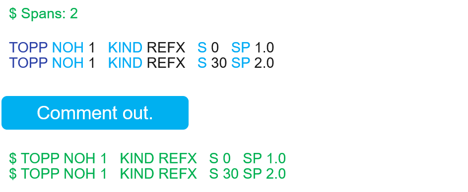
Step 11. Spans Along the Reference Axis
As referring to the geometric point within the cross-section later, comment this input out.
Step 12. Definition of the Tendon Geometry
This part of the text input is about the tendon geometry and refers to the geometric axis definition of step 10.

Step 13. Constraining Point Along the Stations
This record defines a single constraining point of the tendon geometry along the geometric axis. As the reference will be a geometry point within the cross-section comment the entire input lines out and replace it with the input shown in step 14.

Step 14. Referring to Cross-Section Point
In this step, the defined geometry point T101 within the cross-section is assigned to be used as a reference point along the entire axis.

Step 15. Construction Stages
In this part of the input, the assignment to the construction stages happens. This workflow requires no change here.

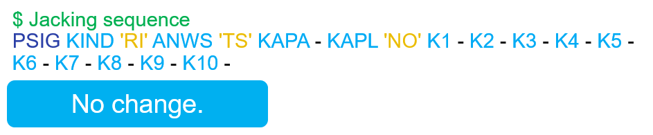
Step 16. Jacking Information
This part covers the jacking behaviour. Again, no change needed here.
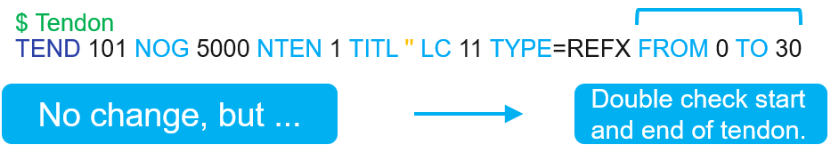
Step 17. Checking the Start and End Point of the Tendon Geometry
There is no action required at the final step. However, it’ recommended checking the start and end of the tendons.
There is a lot going on in steps 9 – 17, so check out the workflow in the video too.
Wrap-up
All over the above workflow brings a huge benefit when it comes to more complex and highly parametrised cross-section. The fact connecting the tendon geometry to a specific point within the cross-section makes it really powerful. On the other hand, the tendon wizard within SOFiPLUS and is capable to do a great job for 99% of your projects. For the last 1% referring to a geometry, point might be the way to go.
Software version: SOFiSTiK FEA v2018-01.
