System Information Dialog Box v2022
When starting a new project in SOFiSTiK FEA, the first thing is to get the project properties right. Options such as the project directory and name, design code system type and more are listed in the System Information Dialog Box.
In version 2022, a few things have changed how to specify those settings. And in this post, I’d like to highlight these for you.
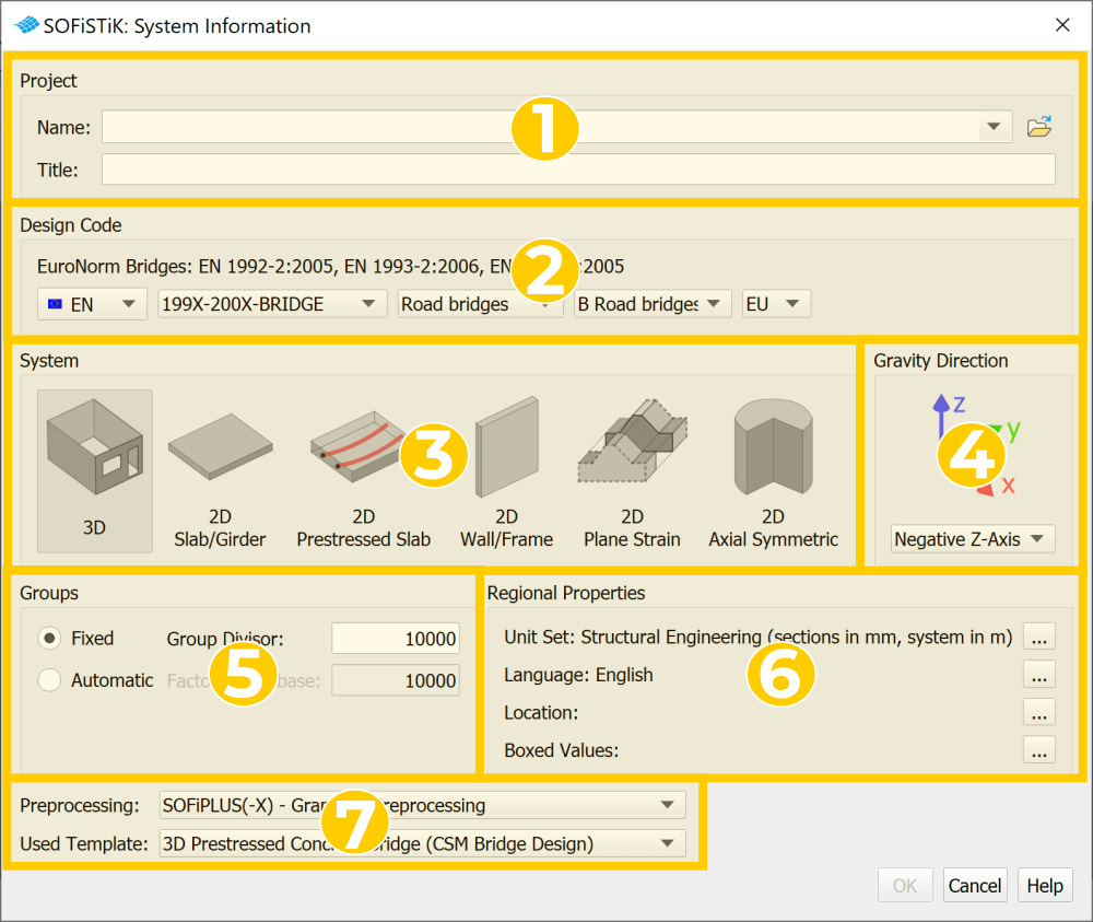
#1 Project Information
The first thing to do in a new project is picking a project name and a location to store the input and output data. If you work in a network environment in your company, please keep in mind that saving and calculation time might increase by selecting network drives.
The Tite input represents the project title and shows up on any printouts.
#2 Design Code
This section of the System information Dialog Box is about the selection of the required design code. For EN Design Codes, the options to pick have changed slightly with version 2022.
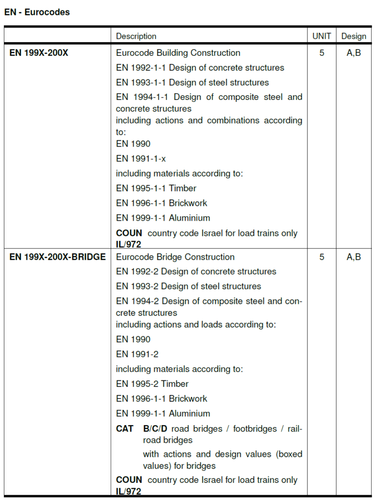
Selection of EN Design Codes
Until version 2020, selecting the Eurocode design codes was based on the design code document; it relayed on the material type. This changes in version 2022.
The selection now no longer depends on the material to be used in the project; it is required to decide which document to use
- the original Eurocode or a national annexe and
- the type of the project, if it’s a building or bridge structure.
It makes the workflow much more straightforward, as in earlier versions.
But how does the input change in the text input?
Withing AQUA, the programme module to define the design code, it looks like the following
- For Buildings: NORM EN 199x-200x
- For Bridges: Norm EN 199x-200x-BRIDGE
You can find further input options whin the AQUA User manual.
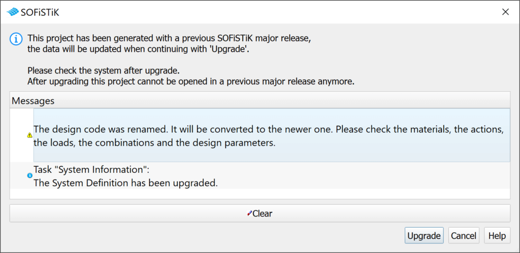
What about converting older projects to the new design code input?
If you are using SOFiSTiK already, then one of the first thoughts coming up in your mind might be; what happens to my existing project when I open it in version 2022.
If you are working with graphical tasks and open your 2020 project in version 2022, the internal mapper will update relevant information for you. And a pop-up will inform you about the design code update. More precisely, it says that the old design code has been renamed to the new one.
By using the Text Input, no automatic mapping takes place, and you will have to take care of the update of the input yourself to convert your project entirely.
If you don’t update the input, there will be a warning inside the protocol telling you about a missing INI-file and which EN Design Code is used instead. I recommend amending the text input to avoid the warning.
#3 Selection of System
You can find the following system types to start your project within the section System:
- 3D
- 2D Slab/girder
- 2D prestressed Slab
- 2D Wall/Frame
- 2D Plane Strain
- 2D Axial Symmetric
#4 Gravity Direction
Depending on the selected system and pre-processor, the direction of gravity changes automatically. However, you can always interfere with the selection as the project input requires. Six options are available POSITIVE X, Y, Z and NEGATIVE X, Y, Z.
#5 Groups
Select one of the two options to control the behaviour of the numbering and group assignment. To learn more about the Group Divisor and its impact, read the post Group Divisor and Factor Group Base.
#6 Regional Properties
This section allows you to specify specific project parameters.
- Unit Set
Allows changing the input and output units of your project. There are a few predefined sets available. However, modifying one or more specific units of these templates is possible. - Language
English and German are available as input languages only.
For your output language, you can select English, German, Spanish, French, Greek, Italian or Russian. - Location
This allows you to define the project location and influences the combination factors of the selected design code. Your model can be set up based on the zero levels, no need to place it to the original geometrical height. - Boxed values
This is a brilliant one. It allows influencing specific code-related factors of design, loads and combinations. The purpose of this feature is clear; it enables you to cover additional national annexes besides the implemented ones.
#7 Pre-Processing Options
Build your models with one of the available pre-processors. Pick the most efficient one to ensure your project model delivers the best possible results.
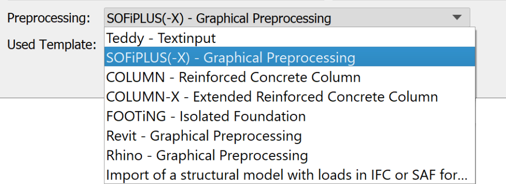
Teddy – Textinput is the numerical input of SOFiSTiK and allows you to set up your project geometry and loads text-based by utilising the graphical tasks of SOFiSTiK Structural Desktop.
SOFiPLUS(-X) – Graphical Preprocessing is an AutoCAD add-on to do the graphical pre-processing. SOFiPLUS allows you to build models utilising native AutoCAD commands and transfer those elements into relevant analytical members. The created system is stored in the native dwg file.
COLUMN – Reinforced Concrete Column
When choosing Column, you will get a predefined template to design a single column by entering loads, eccentricities, combination rules. The analysis will be done based on the nominal curvature method. Running a fire design is possible too.
COLUMN-X – Extended Reinforced Concrete Column
The extended Version of COLUMN allows running the analysis of user-defined cross-sections (Cross Section Editor within SOFiPLUS) and coated steel cross-section.
FOOTING – Isolated Foundation
The SSD task FOOTiNG allows based on given loads to calculate the necessary foundation dimensions. Footing allows assigning vertical forces, moments and horizontal forces. Required design combinations are automatically determined.
Revit – Graphical Preprocessing
Since BIM becomes an essential factor in construction industries, it is also crucial to provide a direct interface to such technology. By using Autodesk Revit as a pre-processor and SOFiSTiK Analysis + Design, the analytical model, loads, and actions can be transferred directly to the SOFiSTiK database – a seamless interface. Furthermore, this workflow allows generating 3D rebars in Revit based on the design results within SOFiSTiK FEA.
Rhino – Graphical Preprocessing
The interface for Rhino works almost in the same way as SOFiPLUS for AutoCAD. It allows you to transfer nodes, lines and areas and support conditions to structural elements considered when exporting to SOFiSTiK FEA.
Import of a structural model with loads in IFC or SAF format
The SOFiSTiK IFC Import feature enables the exchange of structural models in the OpenBIM environment using IFC file format. The model can originate from any other structural analysis software.
The SAF format is based on Excel and is an initiative from the Nemetschek Group to improve the collaboration between structural engineers by developing an open exchange format for exchanging data between structural analysis software. The documentation of the SAF format can be found here: https://www.saf.guide/
To make the most critical input tasks available in the Project Navigation of SOFiSTiK Structural Desktop straight out of the box – you can pick from a few predefined templates.
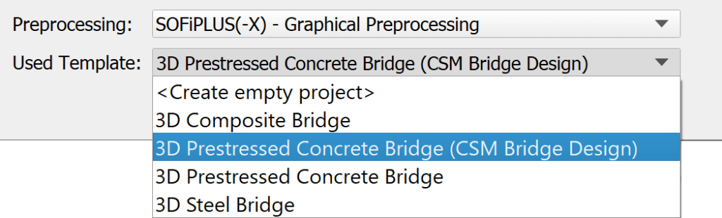
- 3D Reinforcement Concrete Building
- 3D Steel and reinforcement Concrete Building
- 3D Steel Building
- 3D Generic Building (Seismic Analysis)
Besides, you can start from an empty Project Navigation too.
Software version related to this post: SOFiSTiK FEA v2022-0.
