Post-Tensioned Slabs in Revit 2020
This post is about how to define post-tensioned slabs within Revit 2020. You’ll learn about the different steps of the workflow and principals.
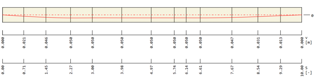
The definition of Tendons in Revit is done by a simplified method. Basically, Revit model lines represent the projection of the tendon geometry in the plan view. And model lines crossing them create intermediate high points of the geometry.
Before we get started, keep in mind the following workflow is only available in Revit 2020 and SOFiSTiK 2020.
A quick overview of the example used to talk through the workflow.
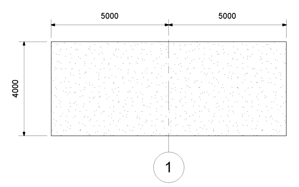
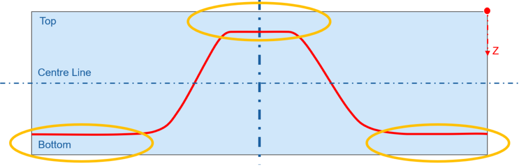
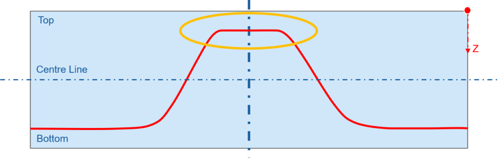
The tendon geometry is defined by two high points, one at the start and one at the end of the slab.
Define Revit Model lines
The first step in the workflow is to create the model lines which represent the tendon projection in plan view. You’ll find the “Model Line” command at the Revit Ribbon “Structure” within the tab “Model”. Ensure to draw the “Model Line” on the correct level.

It’s up to you to draw all model lines before creating the tendon geometry with the SOFiSTiK “Create Tendon Projection” command. Alternatively, one by one. It doesn’t make any difference in the workflow. Every model line must be defined as a tendon geometry to be considered as such in the project.
Create Tendon Projection
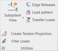
The command to create the tendon projection out of model lines can be found in the “SOFiSTiK Analysis” Ribbon within the tab “Utilities”. Click on the black arrow next to the name Utilities to expand the tab.
Select “Create Tendon Projection”. In the left bottom of the Revit application window, you get asked to pick the model lines.
After selecting all model lines, confirm by clicking the “Finish” button.
Immediately after confirming – all selected model lines change to the line style “SOF_TendonProjection”. Bold magenta lines represent the tendon projections — no chance to overlook them. If you can’t see them, please check the filter settings in Revit.
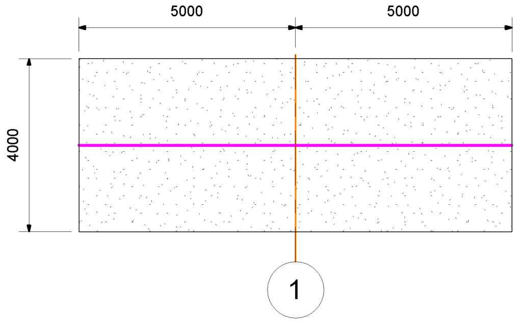
In addition to the Tendon Projection, the gridline changes to the bold orange line. It was recognised as a “Tendon Duct Station” automatically.
I’ll come back on the “Tendon Duct Station” a bit later.
Now let’s have a look into the properties of the Tendon Projection.
By selecting the tendon, the element properties of Revit shows something like in the graphic below.
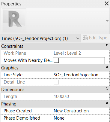
The most important information is the Line Style. It indicates “SOF_TendonProjection” which is mandatory.
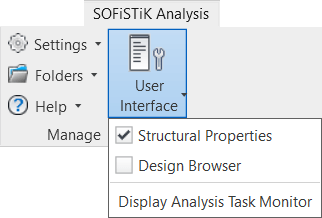
However, to get to the geometry and calculation related properties, it’s required to open the “SOFiSTiK: Structural Properties”. If you can’t see them, you might need to activate them first.
You can find them in the “SOFiSTiK Analysis” ribbon in the tab “Manage”. Click on “User Interface” and activate the “Structural Properties”.
Tendon Projection Properties
There are quite some properties to enter or modify.
General, Geometry, Construction Stages and Prestressing are the four sections. Let’s go through them one by one.
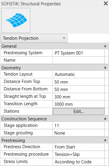
1 General
Besides entering the name of the tendon, you need to decide which prestressing system should be used. The Latter input is mandatory.
How to define Prestressing Systems.
2 Geometry
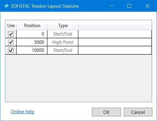
The first option “Tendon Layout” allows choosing between the “Automatic” and “User Defined” layout. The default option is “Automatic”. It enables you to control all duct stations globally based on the following inputs.
Distance From Top / Bottom
Straight Length at Top:
Transition Length:
Stations:
The “SOFiSTiK: Tendon Layout Stations” dialogue box is limited to an on/off the checkbox for every single station.
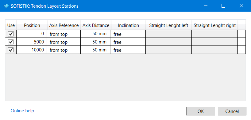
The second available option of the “Tendon Layout” besides “Automatic” is “User Defined”.
The “User Defined” option allows to define every single station fully manually in the “SOFiSTiK: Tendon Layout Sections” dialogue box.
Independent on the selected “Tendon Layout” the tendon shape is generated based on a free tendon geometry. The name is influenced by the fact that no supporting elements are required to define the shape. The tendons are connected at the high points with the upper reinforcement at two places and hang completely loosely in between. The tendon lies on the lower reinforcement and is kept in position with a simple wire attachment. At the transition zone from the lower to the upper reinforcement layer, no further support is required. The tendon is positioned to the centre of the slab at the anchors.
3 Construction Sequence
The input at “Stage application” indicates the stage the tendon is going to be stressed. This input is mandatory for the construction stage analysis later. If you need to consider the grouting process also, please enter a valid stage number in “Stage grouting”. As the grouting is done after the stressing – the number needs to be larger than the one of the stressing stage.
4 Prestressing
This section represents how stressing takes place. Enter information such as the direction of stressing, the procedure and defining the stress limits.
Create Tendon Duct Stations
To every new Tendon Projection, two tendon duct stations are assigned as a minimum. At the start and the end of the tendon geometry. For adding further tendon duct stations, two options are available.
1 Utilising Grid Lines
The command recognises grid lines automatically as tendon duct stations, or in other words as high points. A quite useful feature if the tendon layout is related to the grid system.
2 Utilising Model Lines
Besides the grid lines, any random model line can be used as a tendon duct station. The only thing to do is to change the line style to “SOF_TendonDuctStation”.
Independent of the option you prefer it becomes mandatory that the lines or grid representing the tendon duct station is on the same level as the tendon geometry to intersect.
There are no further options available for the tendon duct stations. Further settings are available in the tendon projection properties.
Generate the Finite Element Model
The last step in the workflow is to generate the tendon geometry in the database to use it further in the calculation and design.
Ensure you saved the project and you have set the “Analysis Settings”.
The “Analysis Settings” can be found in the “SOFiSTiK Analysis” ribbon in the tab “Analysis”.
Activate the 3D view. Click on the “Analyze” command next to the “Analysis Settings” to open the “SOFiSTiK: Analysis” Dialog box.
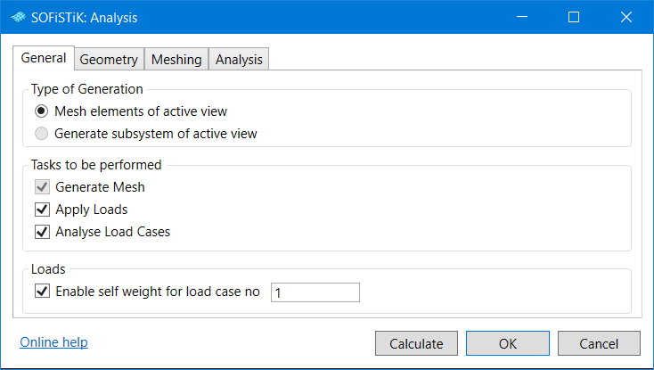
You can leave everything on default. However, I recommend to tick the checkboxes “Analyse Load Cases” and “Enable self-weight for load case no 1”. The analysis for the self-weight load case starts straight after clicking on “Calculate”. It’s nice to get the results to check the system for any problems.
There are no tendon results available after this calculation.
How to calculate the Tendon Forces using the Construction Stage Manager.
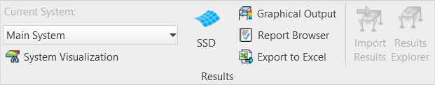
Check the tendon geometry and results of load case 1 by opening SOFiSTiK Structural Desktop straight after the calculation completes. You’ll find the SOFiSTiK Structural Desktop (SSD) Application in the “SOFiSTiK Analysis” ribbon in the tab “Results”.

If you open SOFiSTiK Structural the first time, you’ll need to select a template.
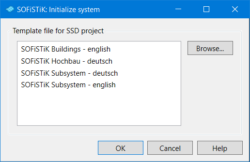
Mainly there are two templates available – Buildings and Subsystem.
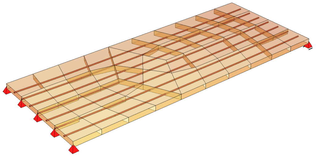
Within SOFiSTiK Structural Desktop you’ll find your structure in “System Visualisation”. If you can’t see the tendons – activate the transparency of the slab. The “Show transparent” command is in the ribbon “View” within the tab “Detail”. There is also the command “Tendon”, which allows switching the tendons on and off.
The structure is now transparent what makes checking the tendon geometry much more accessible.
Check the Geometry and Losses
Having the tendons in the system is excellent. However, double-checking the tendon geometry and properties in more details is recommended. Access the detailed information in the “Report Browser”. The application can be found within the “SOFiSTiK Analysis” ribbon in the tab “Results”.
Besides the textual output, graphics for the geometry as well as losses are available.
Read also the How to Create Post-Tensioned Slabs in SOFiSTiK SOFiPLUS post and learn about an alternative input besides Revit as a preprocessor.
That’s the workflow to create tendons in Revit for slabs and to check the entered information within the “Report Browser”.
Wrap-Up
Having the capability of generating tendons within Revit brings us much closer to a proper BIM workflow for buildings. The principle of the geometry definition is simple. Utilising Revit model lines as projection line in the plan view as well as tendon duct stations crossing the projection line to adjust the geometry. Similar to the approach in SOFiSTiK SOFiPLUS (AutoCAD).
If you are interested in how to generate PT shop drawings in Revit, watch the SOFiSTiK webinar “Slab-tendons in a BIM-Workflow“
Software version: SOFiSTiK FEA v2020-00 and Revit 2020.1.
