Load Definition in SOFiPLUS
This post is an introduction on how to create loads in SOFiSTiK SOFiPLUS. SOFiPLUS is an AutoCAD add-on developed to perform the graphical pre-processing for your structures. Besides using structural elements to build the model – capabilities to define loads are part of the add-on.
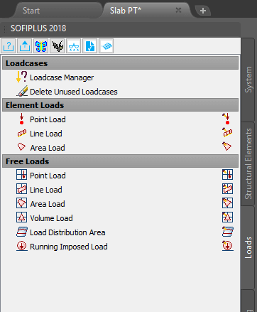
All available commands in SOFiPLUS are well organised in several tabs in the SOFiPLUS sidebar. The third tab “Loads” of the SOFiPLUS sidebar, comes with all relevant commands to create loads.
Within the “Loads” you’ll find three major sections:
1 Load cases
2 Element Loads
3 Free Loads
Load cases
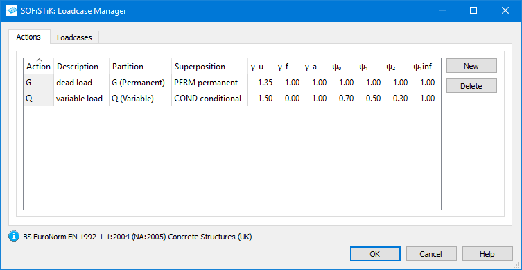
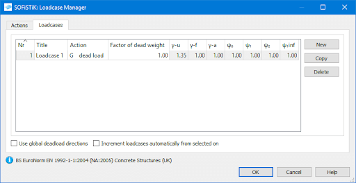
Before you can apply a load to your project “Action” and “Load Case” container must be defined. The single load cases of the structure are stored in the “Load Case” numbers. Every single “Load Case” can be assigned to one “Action” container. Latter is important to perform combinations afterwards.
1 Loadcase Manager
Add a new “Action” within the “Actions” tab by using the “New” button. To remove it, select the “Action” and click the “Delete” button. The table contains also information about the safety and combination factors based on the chosen design code.
Open the second tab “Loadcases” to create a single load case by clicking the “New” button. The “Copy” command is quite useful as all existing loads of the reference load case are going to be copied in the target load case. Select and click the “Delete” button to remove a load case in the project.
Entering a name for each single load case absolutely makes sense as recognising them during the post-processing is much easier. Don’t forget to assign the “Action” from the dropdown menu. In addition to the previously defined actions the action “NONE” and “IMP” – latter stands for imperfection – are available. The “NONE” action is relevant to avoid double consideration of loads when using construction stages.
Read more about combinations
Superposition Manager – Combination Rules
Superposition Manager – Actions
Superposition Manager – Load Cases
2 Delete Unused Load cases
To my opinion this command is controversial. Imagine you created a bunch on load cases but haven’t assigned any loads to it. Clicking the “Delete Unused Load Cases” deletes all empty load cases. Which can be quite annoying, when doing it by mistake. Luckily there is another pop-up which needs to be confirmed before the load cases are going to be deleted.
The pop-up window shows up also if there are was an empty load case recognised during the export.
Element Loads
Now as you heard about defining actions and single load cases let’s focus on the actual load creation.
There are “Element Loads” and “Free Loads” available. Element loads are applied to elements such as structural points, lines and areas. Free loads – point, line, area and volume loads – aren’t linked to any structural element type.
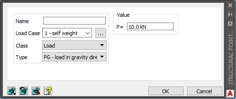
Independent of the structural element type – the graphical user interfaces have two mandatory sections in common. Obviously the load value but also more specific inputs such as the
- load name,
- load case number to assign the load,
- the class of the load and
- the load type.
Depending on the element (point, line or area) choose between different options for “Class” and “Type”. Some of the options of “Class” are factor, load, moment, displacement strain and temperature. The type sets basically the load direction in accordance with the selected element. (“Load in the gravity direction”, “load in local directions”, “load in global directions”)
The load information is connected to the element until you remove the load properties again or you delete the element.
1 Point Load
Create a structural point in the compact “Structural Point Load” dialogue box by entering the basic information such as load case number, class, type as well as load value. There is actually nothing else you can do besides confirming or cancel the input.
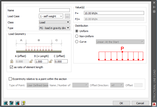
2 Line Load
The “Structural Line Load” command provides the most available options to assign a load. Besides the basic information, it is possible to apply more details such as load geometry, load distribution and load eccentricity.
Load geometry allows you to consider offsets of the load. Activate the required input field by clicking the padlock symbol. Enter the values as a ratio or as a measure of length.
Select one out of three options to distribute the load along with the element. Uniform, Non-Uniform and Curve. The curve option allows you to create a linear, quadratic and cubic distribution.
Last, but not least, assigning the element load to a specific point within the cross-section definition is possible. Depending on the use of standard or user-defined cross-sections you’ll get different possibilities. This input section also allows defining a nonlinear temperature load for beam elements.
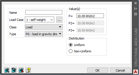
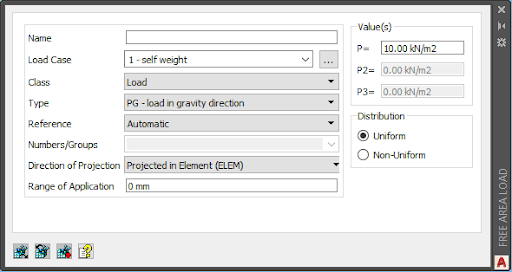
3 Area Load
In “Structural Area Load” you’ll get the option to create a uniform or non-uniform load. The non-uniform option enables three load inputs (“P”, “P2” and “P3”). Those three values create a plane which represents the final load. When creating the load the click sequence is referred to the load values. “P” represents the first, “P2” the second and “P3” the third load value of the non-uniform load plane. Load values from the forth point on are interpolated by the software automatically.
Free Loads
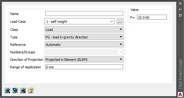
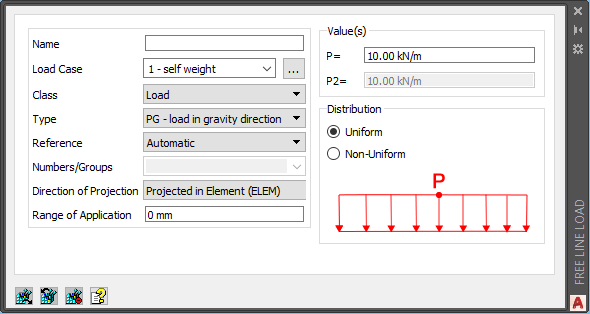
Free Loads aren’t associated with structural elements and can be placed at any location in the project.
The load commands “Point Load”, “Line Load”, “Area Load” and “Volume Load” come with the default inputs as in the element loads. However, as the load isn’t connected to the element anymore – further options such as
- Reference,
- Numbers/Groups
- Direction of Projection and
- Range of Application are available to manipulate the load behaviour.
1 Free Point Load
2 Free Line Load
3 Free Area Load
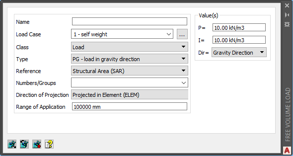
4 Free Volume Load
5 Load Distribution Area
Distributing loads on a grid is supported by the Load Distribution Area command. It basically creates a structural area with particular properties to distribute allocated loads. Besides selecting the affected groups entering the depth of the range is possible.

Read more about Load Distribution Areas in SOFiPLUS.
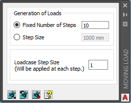
6 Running Imposed Load
The “Running Imposed Load” command performs the distribution of a single load or set of loads along a curve. Based on a fixed number or a specific step – both options are available.
Read the more about Running Imposed Loads in SOFiPLUS.
Wrap-Up
Besides the strong graphical modelling capabilities of SOFiPLUS defining loads is extremely powerful. The fact SOFiPLUS uses native AutoCAD commands makes creating and modifying load elements simple. Tools such as “Load Distribution Area”, “Running Imposed Load” as well as the capability to copy entire loads from one to another load case will save valuable time in the project.
Software version: SOFiSTiK FEA v2018-09.
