Incremental Launching – Principles and Workflow
The challenge you’ll face analysing and designing a bridge – using the incremental launching method – is for sure the massive amount of construction stages as every single stage represents a new analytical system. Furthermore, the final design requires a consideration of the results of every single stage.
Creating for every stage a separate model is possible but very time-consuming – not to speak of maintaining those models. Luckily, the construction stage manager of SOFiSTiK allows you to work on one single model to avoid creating models for every construction stage.
Components of Incremental Launching
There are a few main components to consider in incremental launching when building the actual structure but as well when doing the analysis and design.
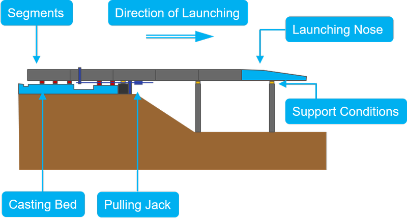
+ Segments
The segments are the major part, as they are representing the final bridge after the finished launching.
When preparing the model for incremental launching the final state of the bridge is modelled. The launching sequence will be controlled afterwards within CSM. However, it is most important to set up useful group numbers of the segments, as it will be activated in CSM.
+ Supports
During the launching process, it’s most important to reduce the friction at the supports. Therefore, materials with very low friction coefficients are mandatory. In the analytical model, the spring stiffness of the support needs to be adjusted and verified to the finally used product.
+ Casting/Launching Bed
Most of the segments are poured on site – some are prefabricated. But both have something in common before getting launched – they need to line up to successfully launch. And to get them in the right position the launching bed is required. As the supports, the launching bed is simulated with spring elements with a verified stiffness.
+ Pulling Jack
To pull or push the segments along the alignment specific equipment is necessary. Depending on the complexity and size of the structure investigating in different types and approaches might be required.
+ Launching Nose
Especially when launching a long cantilever reducing the weight of the beginning of the structure is of benefit. The launching nose is made of steel and way lighter than the final concrete structure.
Principals of the Workflow
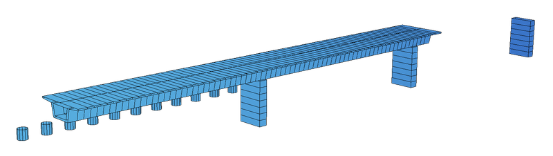
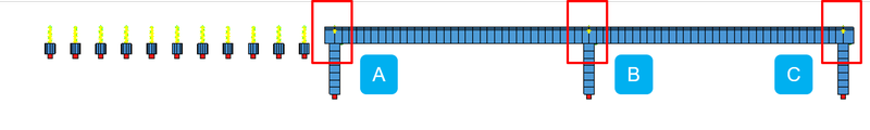
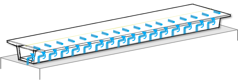
The best way to illustrate the workflow is on a simple example such as a 2-span beam bridge. The graphic below shows the structure with the first span already launched and the second span still placed at the launching bed.
+ Modelling
As for every other project setting up the structure is necessary. As usual, both options – the graphical input and the text input CADiNP – are possible. In the following example, SOFiPLUS was used.
In general, there is no limitation for the model. However, as incremental launching requires a proper construction sequence considering a useful group numbering system is recommended and will save a lot of time later in the workflow.
As the “SOFiSTiK Construction Stage Manage” handles the launching, you can set up the structure straightforward in its final stage. No need to spend hours on creating a separate model for each different launching stage.
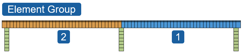
1 Segments
The segments are one important part of the structure as those represent the moving parts in the entire process. So ensure
- A proper group definition related to the launching sequence and direction.
- To keep gaps in the group numbers between major launching steps.
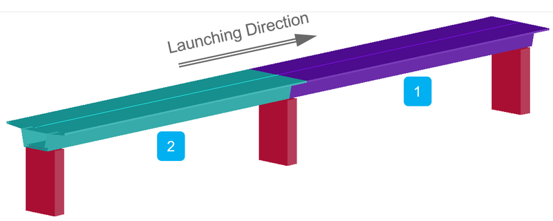
2 Support Conditions
Actually, besides the segments, the support conditions are the major part in the entire incremental launching process. The most important – spring elements are mandatory.
- Incremental launching requires spring elements for support conditions.
- No second reference point required for point springs.
Expected support stiffness essential and needs to be verified.
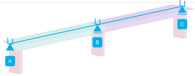
The graphic above shows the 2-span bridge in its final stage, with the highlighted 3 supports A, B and C. Assigning different springs with different groups in each direction is an essential factor to control the incremental launching process.
Don’t forget the casting/Launching bed which is located at the beginning of the structure. It’s important to assign a useful spring stiffness also.
Before jumping to the support definition there is one very important detail. To utilise the spring elements for incremental launching they need to be upgraded to a moving spring element.
3 Moving Springs
The contact between the superstructure and substructure during the launching process is guaranteed by moving spring elements. To break it down, the moving spring element is a more advanced spring element. The possibility of connecting with the structure – without a direct contact – in spring direction as well as transversal to the spring direction makes it the perfect application for incremental launching.
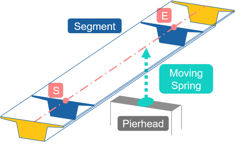
- Generally placed on the pier heads and pointing in direction of the superstructure – upwards.
- The moving spring element is defined with one single point only (single spring).
- The pointing direction of the moving spring is independent of beam start and end nodes. Intermediate contact possible.
4 Support A
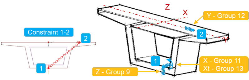
Support A represents the fixed support in the final stage. With this and the moving springs in mind – spring elements in the modelling process are mandatory. And how it looks like in detail is shown in the graphic below.

In the model two structural points – one at the bottom of the structure (1) and one on the right side (2). Both structural points (1) and (2) are connected to each other with a rigid constraint. And haven’t any contact with the superstructure (structural line) at all. However, it is important to point the spring element to the structural line to allow the moving spring finding the element to connect.
Structural Point (1):
Point (1) is responsible for the axial stiffness in Z and X Direction as well as for the torsional stiffness in X Direction. In this example, the stiffness is set for all springs to 1E7. To upgrade the spring elements to moving springs it is mandatory to assign different group numbers to each spring element.
Stiffness and Group:
Z … 1E7kN/m – Group 9
X … 1E7kN/m – Group 11
Xt… 1E7kNm/rad – Group 13
Structural Point (2)
Point (2) is used to control the structure in the transversal horizontal direction. As in point (1), the stiffness is set to 1E7.
Stiffness and Group:
Y … 1E7kN/m – Group 12
5 Support B+C
Support B and C are representing the moving support of the 2-span bridge. The location of the springs are equivalent as in support A. However, the stiffness in X Direction needs to be modified to allow the horizontal displacement.
Stiffness and Group:
Z … 1E7kN/m – Group 9
X … 1 kN/m – Group 11 – Changed to 1 kN/m
Xt… 1E7kNm/rad – Group 13
Stiffness and Group:
Y … 1E7kN/m – Group 12
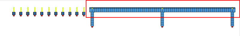
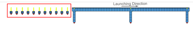
6 Casting/Launching Bed
Before the segments are going to be pushed or pulled to its new position, they will be prepared in the Casting/Launching Bed To consider this step of the incremental launching process in the analysis the Casting/Launching Bed needs to be modelled. Again spring elements will be used and upgraded to moving springs.
As a stable system for calculation is required in any case.
- Support in the vertical direction.
- Support in the X Direction (minor resistance – launching direction)
- Torsional support around X direction
- Transversal support, Y direction
As those requirements are similar as for support B and C, the same setup is used. However, depending on the circumstances the spring layout and stiffness need to be verified.
Stiffness and Group:
Z … 1E7kN/m – Group 9
X … 1 kN/m – Group 11 – Changed to 1 kN/m
Xt… 1E7kNm/rad – Group 13
Stiffness and Group:
Y … 1E7kN/m – Group 12
+ System Modification – Moving Springs
Let’s talk about the necessary upgrade of the support springs to moving springs. Although the workflow was done graphically until this point the following steps require the text input.
The modification of the spring elements can be done in the program module “ASE”.
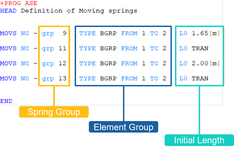
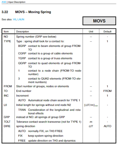
The command “MOVS” allows assigning a specific behaviour of the spring element selected by the group number. Before putting the first input line into the text interface Teddy it is important to collect the required information.
The graphic below shows the group numbers of the assigned springs as well as the initial length.
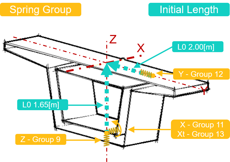
The group number 12 – which represents the spring element responsible for the transversal horizontal direction – points to the structural line of the beam bridge with an initial length of 2.00[m]. Group number 9 – responsible for the vertical support – points upwards to the structural line with an initial length of 1.65[m].
Besides the possibility of assigning a specific initial length in spring direction entering “TRAN” at the item, L0 allows the spring element to look for elements in the transversal direction.
Besides the spring group and the initial length, a third input is required to specify the element type and group number to connect.
A possible input is shown in the graphic below.
If you’re not familiar with the text input yet, the interactive help is extremely useful to understand all the available input possibilities in Teddy/CADiNP.
+ Launching Sequence
In the above, the focus was on the structure and the supports as well as the group numbers. This chapter is about how to set up the launching sequence in the SOFiSTiK “Construction Stage Manager”. Again for incremental launching, the text interface is required. If you are already familiar with the “Construction Stage manager” you’ll find just a few modifications to the required input.
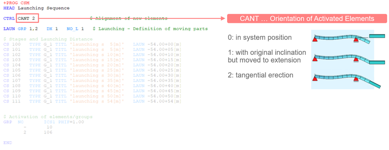
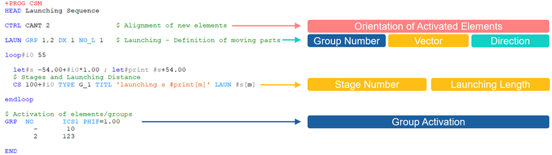
1 Alignment of Activated Elements
It is important to decide how new elements should be attached. Enter the wanted option at the command “CTRL CANT”.
- 0: in system position
- 1: with original inclination but at end of the cantilever
- 2: tangential erection
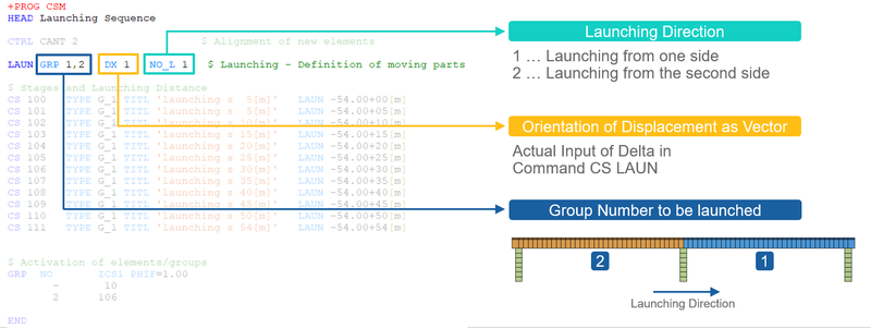
2 Launching Properties
The “LAUN” command allows to decide about the launching direction, the orientation of displacements as well as which group number to be launched are made.
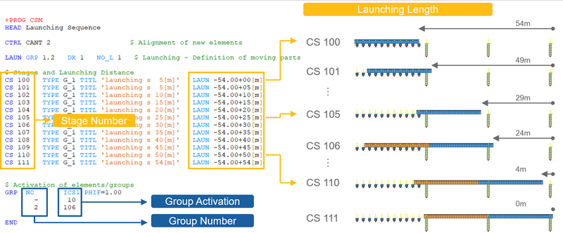
3 Stages and Launching Length
In this stage of the workflow, the actual work begins. Although the most work is done by the program it isn’t avoidable to set-up the stages manually. On the other hand, it’s also a good thing to have as much as possible influence on the sequences.
The command “CS” initiates a construction stage with its number. To get useful results out of the analysis it is required to assign each stage to a Type. However, for incremental launching a further item “LAUN” is available. “LAUN” initiates the shift of the structure in the opposite direction of the launching direction. The stage CS 105 represents the last stage before activating the second span in CS 106.
Additionally to the stages and the shift the activation of the superstructure is required. The command “GRP” allows beside many other options the activation of group numbers in a specific construction stage. Group number 2 – second span – is activated is activated in stage CS 106.
The above input of the construction stages was done line-by-line to keep the input transparent. However, for those are excited to reduce the input lines as much as possible one can use loops too.
Download the 2-Span Beam Bridge incremental launching example (SOFiSTiK FEA v2018, AutoCAD 2018).
Wrap-Up
On the first view, incremental launching seems to be a process of endless construction stages and a huge amount of results to handle. Possibilities such as defining the structure in its final stage, adapting springs to moving springs and setting up the construction sequence in a table prove that the shown workflow for incremental launching in SOFiSTiK is most efficient.
You’ll find further details about incremental launching in chapter 2.10 of the CSM (Construction Stage Manager) user manual, csm_1.pdf. Also, watch the video CSM Incremental Launching on YouTube.
Software version: SOFiSTiK FEA v2018-06.
