How To Align Local Coordinate Systems in SOFiPLUS
There are a couple of reasons for a proper aligned local coordinate system of structural elements. Those I have in mind are:
- load assignment
- stiffness assignment
- reviewing results in post-processing
The “Align Elements” Command in SOFiPLUS allows orientating the local directions of structural elements in various ways. For example, it allows rotating Structural Lines around their longitudinal axis, Structural Areas within their plane and Structural Points around all three axes.
You can find a video at the end of the post if you are more of a visual learner.
Before jumping into the workflow and available alignment options – a quick tip.
The default settings of SOFiPLUS don’t include the visualisation of the local coordinate systems of all structural elements. It is very convenient having them turned on to check changes immediately. You can activate the coordinate systems in the Tab “Tools” in the SOFiPLUS sidebar – section “Options” – “Visualization”
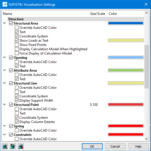
Activate the tickboxes “Coordinate System” for “Structural Area”, “Structural Line” and “Structural Point”.
Where can You find the command “Align Elements”
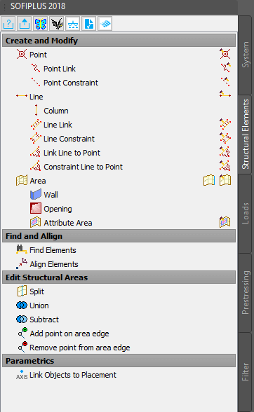
The “Align Elements” command can be found in the “Structural Elements” tab of the SOFiPLUS Sidebar. The section “Find and Align” includes also the command with “Find Elements” – which is a very useful tool to locate elements by their number.
The main steps using the command “Align Elements”
- Click on “Align Elements” in the SOFiPLUS sidebar.
- Select elements you want to align.
I recommend selecting one structural element type only as different ones. You won’t get specific alignment options for certain element types. E.g. if an area is included in the selection with lines, you don’t get the “DI invert direction” option for lines. - Confirm the selection with ”Enter”.
- Chose one of the alignment options available in the “context menu” or in the “command line”.
All alignment options are for different structural element types are listed below. - Close and apply all changes by using the “END” option in the “Context Menu” or the “Command Line”
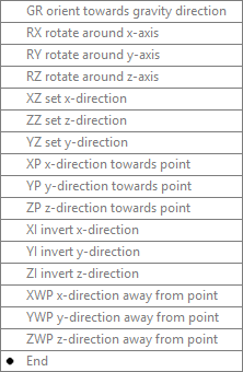
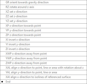
Available alignment options for Structural Points:
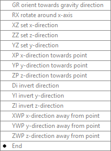
Available alignment options for Structural Lines:
Available alignment options for Structural Areas:
Note, that changing the local directions of structural elements might affect loads applied to the structural elements, local support conditions and the cross-section too. Don’t forget to double-check the results.
Alignment Options
Let’s have a look at the different options.
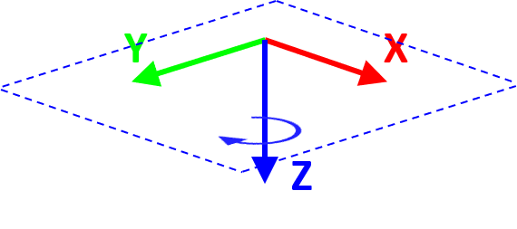
#1 GR Orient towards gravity direction
This command is applicable to different structural elements types. It aligns the local z-direction of all selected structural elements to the global direction set in the System Information Dialog Box. It’ll consider the local z-direction of a structural area must be perpendicular to the plane, the local x-direction of the structural line must point along the line and the right-hand rule must be kept in any case.
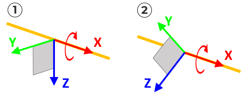
#2 DI Invert Direction
Inverts the direction of the local x-direction of structural lines only.
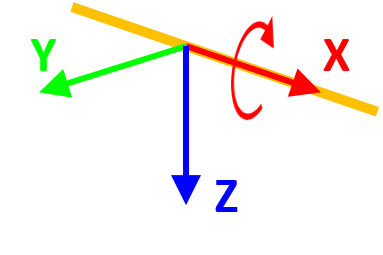
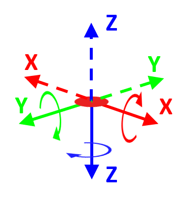
#3 RX Rotate around x-axis, RY rotate around y-axis and RZ rotate around z-axis
Rotates the element about its selected local axes. An optional angle can be entered. Depending on the structural element the following options are available.
Rotation about x-direction: Structural Points, Structural Lines
Rotation about y-direction: Structural Points
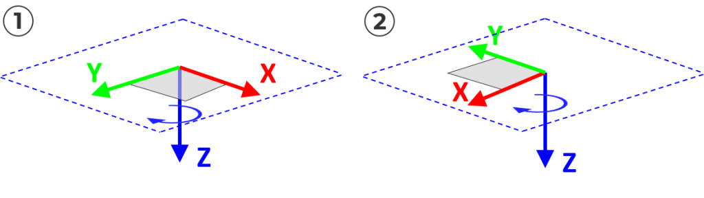
Rotation about z-direction: Structural Points, Structural Areas
+ Structural Points

+ Structural Lines
+ Structural Areas
#4 XZ set x-direction, ZZ set z-direction and YZ set y-direction
The option allows you to define a rotation along a direction by selecting two points by clicking on the canvas. The angle will be calculated and applied to the rotation.
+ Structural Point
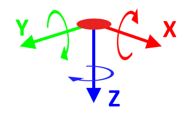
For structural points rotations about all three axes are allowed.

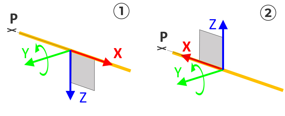
+ Structural Lines
As the local x-direction for structural lines must point in the same direction as the structural line, the “XZ set x-direction” can be used to invert the x-direction of the structural line element only.
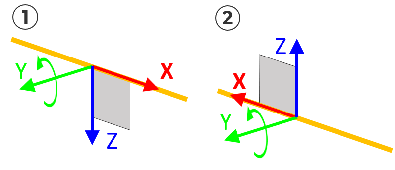
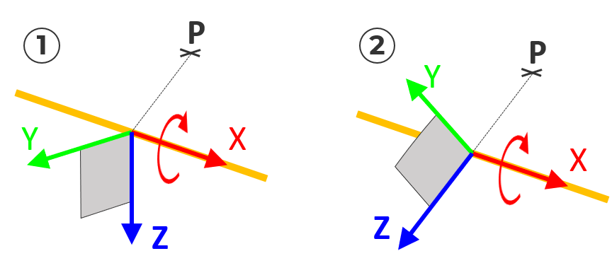
The “ZZ set z-direction” and “YZ set y-direction” options allow you to rotate structural line elements about their local x-axis. The difference to “RX rotate around x-axis” – the option defines the rotational angle by defining two points.
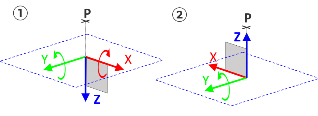
+ Structural Areas
As the local z-direction of structural areas must remain perpendicular to the area, only the z-axis can be inverted by using “ZZ set z-direction”.
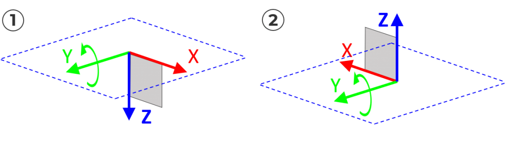
Due to this fact, the options “XZ set x-direction and “YZ set y-direction” allow you to align either the Y or X-axis in the XY plane (around the Z-axis).
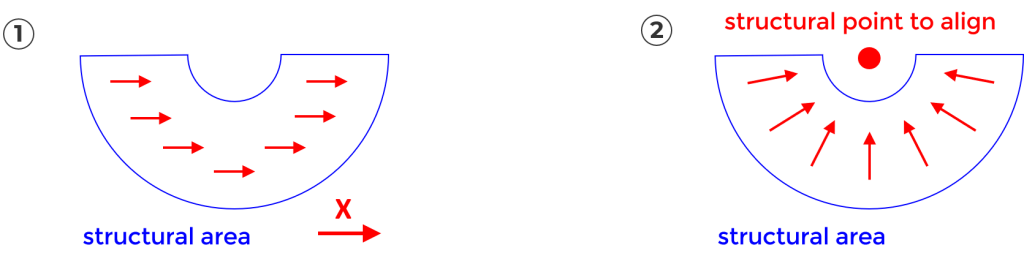
#5 XP x-direction towards point, YP y-direction towards point and ZP z-direction towards point
The allowed rotations are similar to “XZ set x-direction, ZZ set z-direction and YZ set y-direction”. The only difference – the direction will be defined by pointing one single point instead of selecting two points to calculate the rotational angle.
+ Structural Points
For structural points, you’ll get the possibility to rotate along all three local axes.
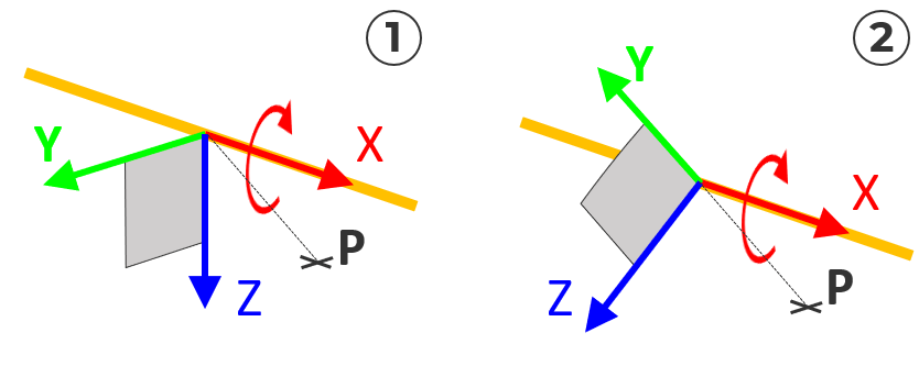
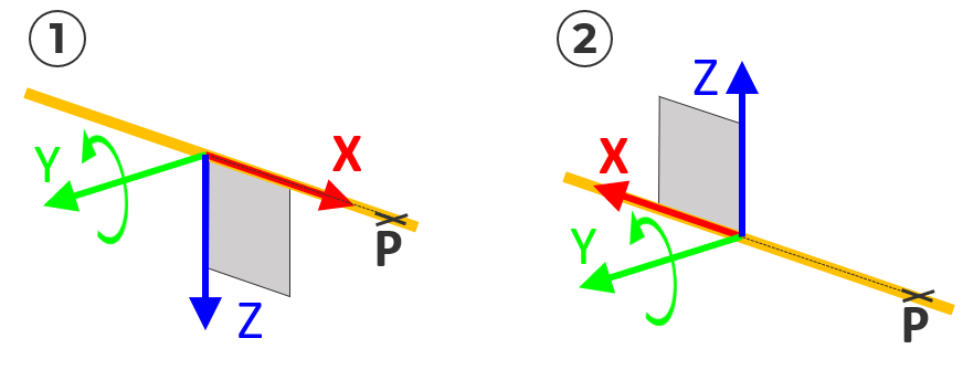
+ Structural Lines
Structural lines must keep the local x-direction along the line direction. So rotating along the x-direction and y-direction is possible.
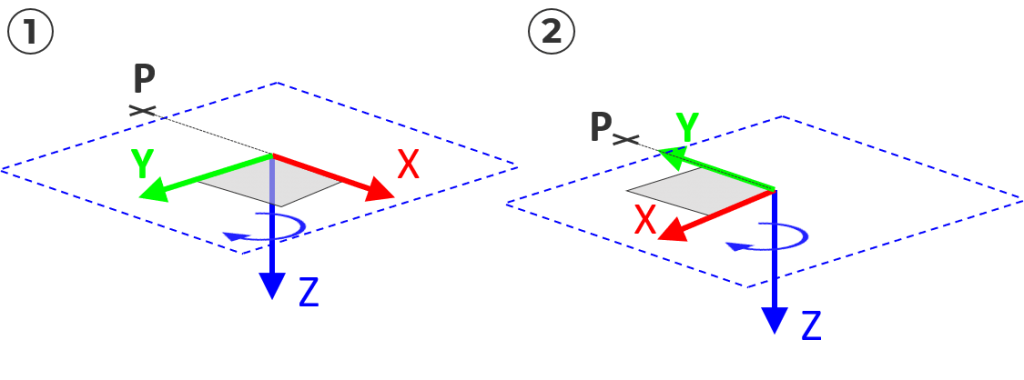
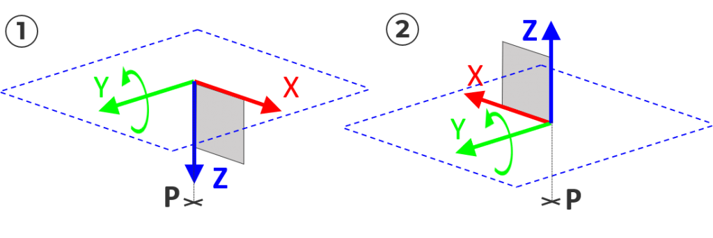
+ Structural Areas
Rotation along the x-direction and y-direction is possible but is more or less an inversion of the z-direction only. The local z-direction must remain perpendicular to the plane.
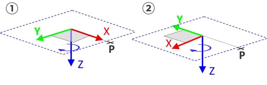
Rotation along the Z-direction is allowed. So aligning the x-direction or y-direction is possible (rotation around the z-axis).
#6 XWP x-direction away from point, YWP y-direction away from point and ZWP z-direction away from point
This option is similar to “XP x-direction towards point, YP y-direction towards point and ZP z-direction towards point”. But aligns the axis in the opposite direction of the selected point.
+ Structural Lines
+ Structural Areas
#7 XI invert x-direction, YI Invert y-direction and ZI invert z-direction
This option reverses the direction of the selected direction by considering the right-hand rule to keep a proper local coordinate system.
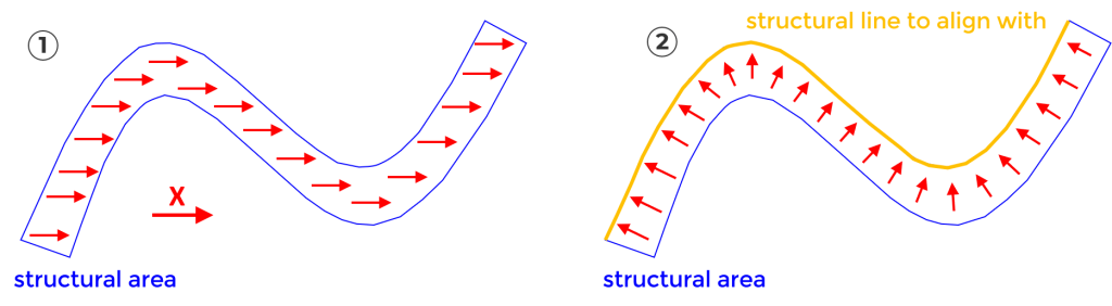
#8 XAL align x-direction to point, line or area and YAL align y-direction to point, line or area (with rotation about z)
This option applies to structural area elements only. The local x-axis or y-axis can be re-aligned by a selection of another existing structural element. An angle for additional rotation of the local z-axis can be assigned also.
#9 XAI align x-direction to isolines of referenced surface
Only structural areas are affected by this option. The local x-axis of structural areas – which was extracted from AutoCAD surfaces – can be re-directed to the original direction.
Watch the Video
Wrap-Up
Aligning the local coordinate systems is a very important aspect and should be paid attention to before investigating results. The “Align Element” command allows you to undertake modification at any stage of the project.
Software version: SOFiSTiK FEA v2018-09.
