How new Design Methods lead to a Different Result Description
Written and presented at the SOFiSTiK Seminar 2018 by:
Atte Mikkonen, DI, Sillat, MSc, Bridges | WSP, Finland
Summary
In modelling of bridges for analyses or for construction, the quick development of the tools is changing the practices and workflows continuously. Applying new methods in design, producing a new format of deliverables and trying to fulfil old requirements will absolutely face challenges that recall for full rethinking. Thu Thiem 2 is a first major bridge to be built in Vietnam, where comprehensive information modelling in design is applied in the country. Kruunuvuori Bridge is a bridge designed to the client, that require maximal utilization of information modelling. Both are challenging cable-stayed bridges where new tools were adopted along the design process. Through these examples, the challenges and future expectations are highlighted from the bridge designer’s point of view.
1 | Thu Thiem 2
Project background
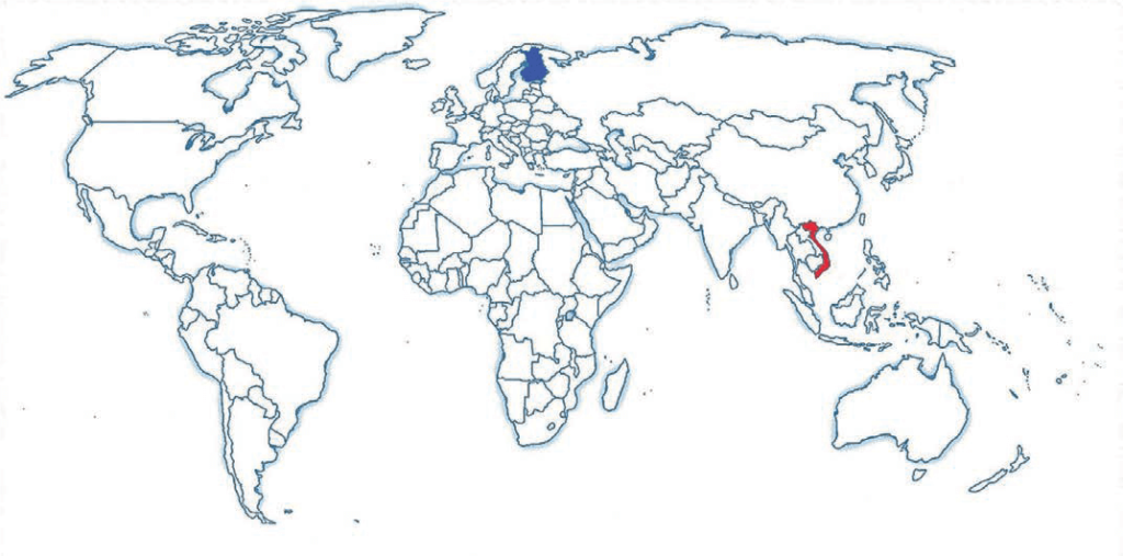
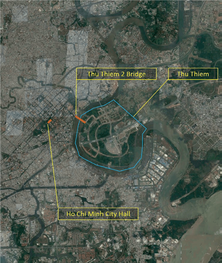
Thu Thiem 2 Bridge is a new crossing to be built over the Saigon River to connect the new Thu Thiem district to the city centre of Ho Chi Minh City in Vietnam. The Bridge location in the heart of a 10 million people metropolis, South Vietnam’s financial capital, sets expectations for high quality, well recognizable and unique bridge. The Bridge is expected to become a symbol, not only to the related Thu Thiem district but also to the whole city.
The Bridge construction works have started in 2017.
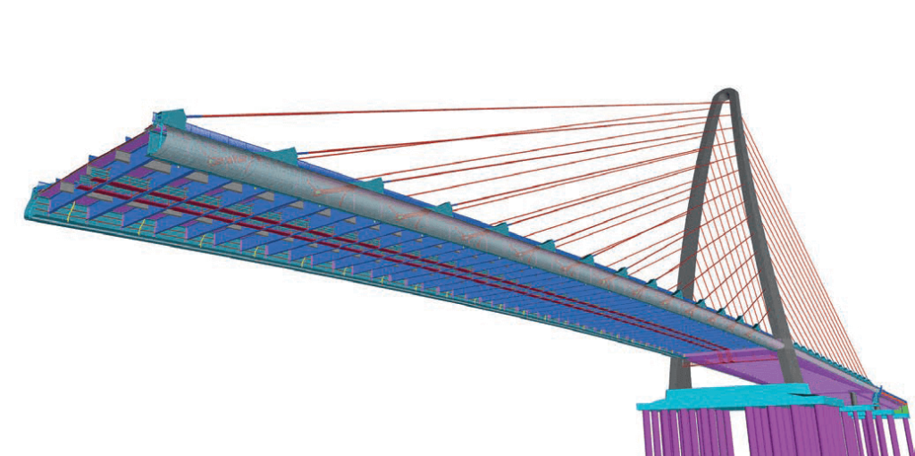
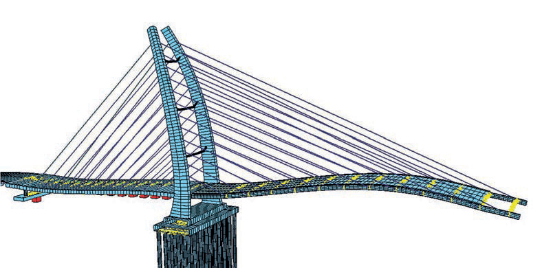
The Bridge is a cable-stayed structure with a single pylon and asymmetric spans of 200 m + 115 m. The longer span includes the main navigational channel and is located on the outer side of the river curve. The main bridge joins to the Ramp Bridges by an expansion joint on the city side and is monolithically joined to the side Spans on the Thu Thiem side. The main characteristic of the Bridge is the pylon with a backwards and smooth curved shape.
BIM in Vietnam
Vietnam is an economically developing country transformed from one of the poorest in the world into a lower middle-income country during the last decades. Development and interest to invest in the infrastructures and construction are strong, and they do have a national interest to apply most modern technologies and methods in the design and construction. They want foreign consultants to bring in practices used in western countries. Authorities actively encourage consultants to propose methods and standards to be used. The same applies to information modelling, which eventually was quite comprehensively applied in the Thu Thiem 2 Bridge design.
Vietnam does not have any national guidelines or recommendations for information modelling yet. For a Finnish consultant, it was natural to propose practice as applied in Finland. The practice in Finland for bridge design is well specified in the recommendations and guidelines issued by Finnish Transport agency [1], City of Helsinki [2] and Building Smart Finland collaboration forum [3].
The Finnish guidelines include general guidelines for design and procurement, for different design stages and tasks and the detailed requirements for the technical requirements, formats, nomenclature etc. which are also proven in practice during the years those are already applied in the country. In Vietnam, the design approval process has high bureaucracy. It was also necessary that the project design documentation fulfils the local traditional requirements and format for approval. Partially overlapping designs (traditional and modelling) were thus required for the project.
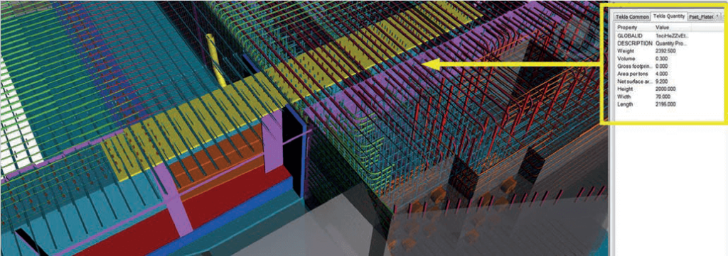
According to the prepared BIM execution plan, the modelling is not prepared in all the details as the traditional designs. Detailing level will provide geometry and material info and is prepared so that the model can be developed further in becoming stages so that the component production can be model based (steel structure single part fabrication, bar bending lists, geometry control etc…).
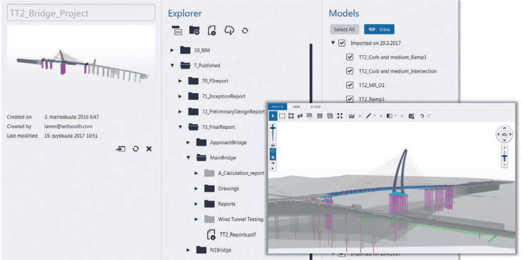
The information model was also used for project management. As the design work was mainly done in Finland, the progress was additionally reported to the Client in Vietnam via cloud-based information model service. The updated model was uploaded weekly to the server so that the client was able to view it by web browser-based interface or download and share the design.
By this arrangement, the client was “real-time” aware about the design development and design solutions, which was found easy and practical. When the design work was completed, there were practically no comments as the client has seen the whole design graphically in 3D and in details before. The model was not used for authority approvals, as the traditional drawings, specifications and bill of quantities were required.
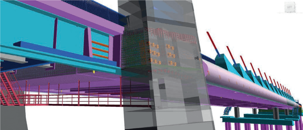

As the project team had a lot of experience in modelling of bridge structures, it was clear from the beginning that the steel structure drawings for the superstructure will be directly produced from the model. During the design process, it was realized, that there is a lot of other components, that are modelled with so good accuracy that the drawings will be most practical to be produced completely model based. At the end of the design, superstructure components were almost completely modelled including all the accessories, pre-stressing and reinforcement.
More or less, the pylon reinforcement was the only major component not modelled at all. Finally, the pylon drawings were the only major item produced by traditional methods, even the geometry and the steel structure accuracy would have been sufficient for model-based drawing production.
Structural design aspects
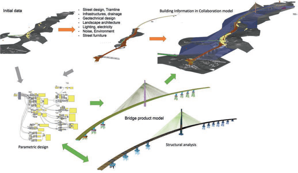
Traditionally the design engineer has prepared the calculations, analysed the structure, and then the assistant has prepared the documentation for the client, drawings or model, for construction or for other purposes. The digital design methods have changed the procedures. The digital structural sketches can be imported to the analyses and respectively the analyse software output information can be transferred to software for production information. Rarely the information exchange is interactive, but whatever the case or method is, the parallel design and analyses will take place more and more in the future.
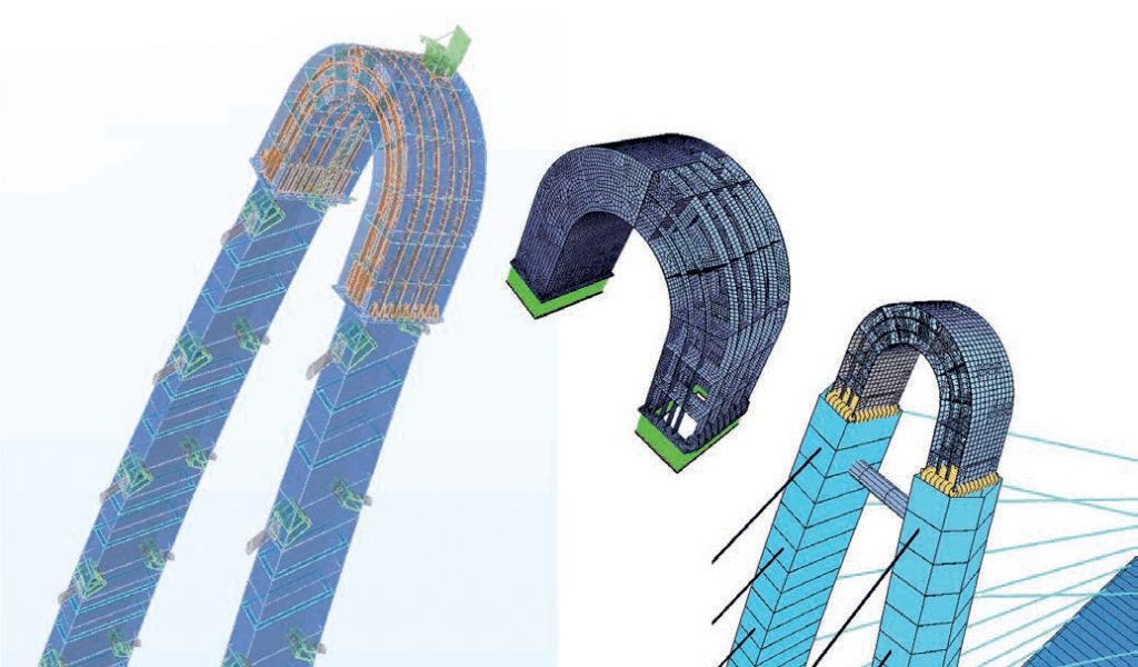
In Thu Thiem 2 bridge design, the geometry of the pylon was an initial challenge; how to design the pylon so that it is also feasible for construction. Certain constants (e.g. geometric axis) were needed to manage the geometry. After the pylon geometry axis and cross-section constants/variables for the geometry control and for the analyse model was defined, it was found out that exactly the same parametrization is possible for the information modelling. The parametrization (variables) in SOFiSTiK was effectively utilized in global analyses models and the same variables were directly used for the information model. Parametric modelling tools have recently developed further for information modelling, so more versatile parametrization was used in steel structure detailing. Detailed steel structure models were then imported into the SOFiSTiK and local models were easily created and analysed.
Finally, the local models were imported into the global SOFiSTiK model. As all the models were using the same coordinate system, the data transfers easy and accurate.
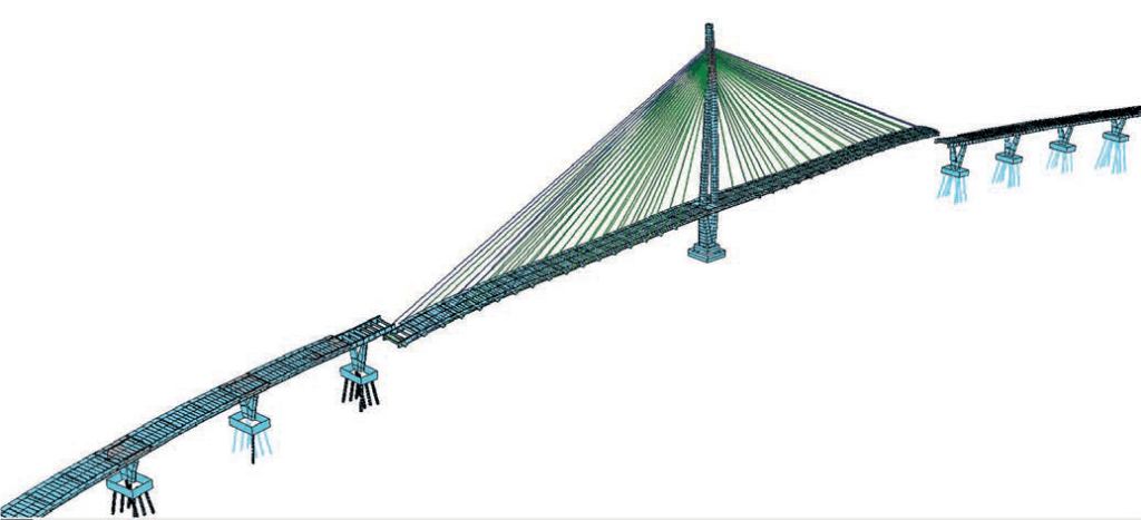
For cable-stayed bridges, symmetry generally provides balance. Not only at the final stage, but also during the erection. In Thu Thiem 2 bridge the pylon is not vertical and the span ratio is not symmetric. In the analyses, the final stage equilibrium is then possible to define so that the gravitational forces from the cables run through the pylon axis not bending it.
It was aspired to do the cable stressing only once, at least for the main span, where the navigational clearance is located. Challenge is that during the span erection, there is a lot of dead load not in place (asphalt layers, concrete barriers…) yet. Due to the missing dead load during the erection, curved-inclined pylon with anti-symmetric span ratio, it was not possible to find a procedure to stress the cables only once without producing too high bending (tensile stress limits) to the pylon.
The found/proposed solution was to leave the back span on its concreting supports for the main span erection. It behaves as a counterweight for the main span, while the back stay cables are stressed little less (to a smaller force) than requested to achieve the final forces with on stressing. The force applied to the back span cables was selected only to balance the force (from the pylon point of view) in the main span cables when stressed to their final lengths. That arrangement requires only restressing for the back span cables, to lift it from its casting supports, and to balance the final cable forces from the main span.
2 | Kruunuvuori Bridge
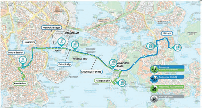
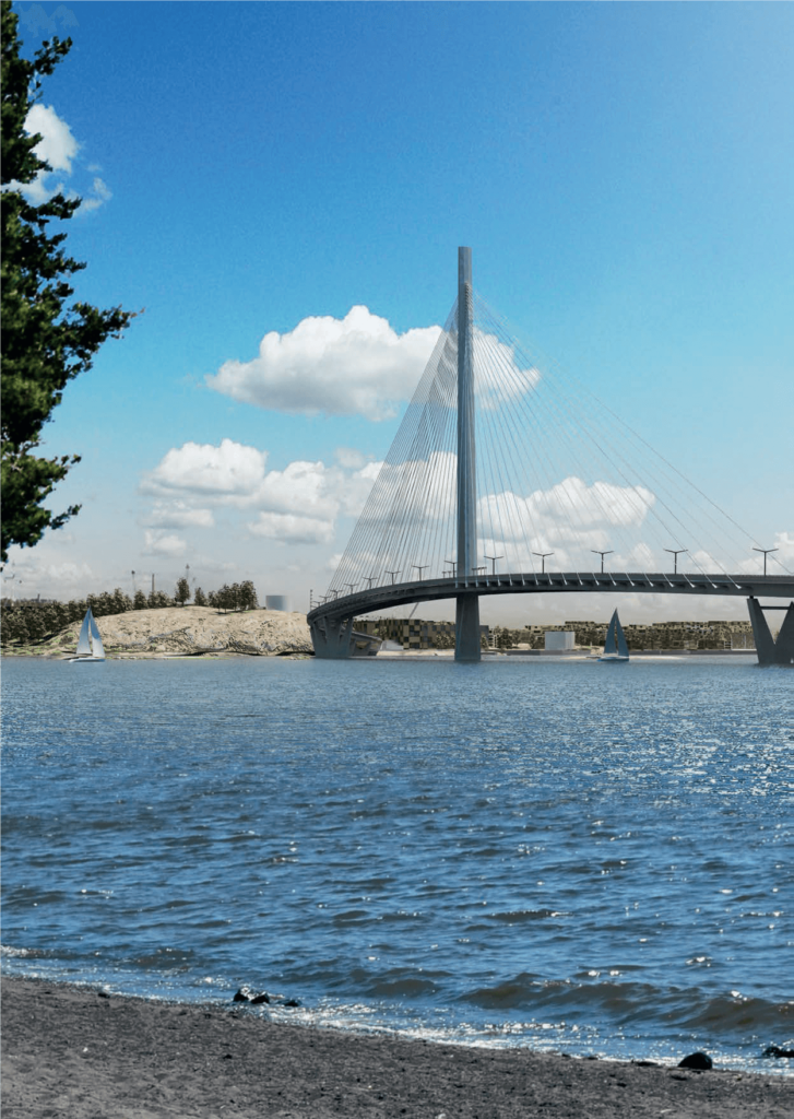
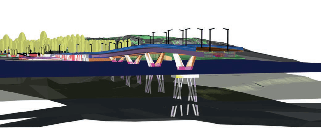
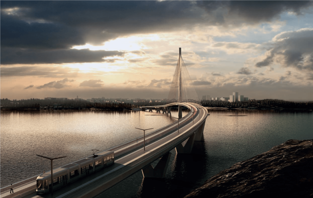
Crown Bridges is an ongoing design project in Helsinki Finland. It’s a new link for trams and cyclists/pedestrians from the city centre to Laajasalo, through a new residential area to be built in Kruunuvuorenrata. The land there has been released for construction by the relocation of an oil depot further east to Vuosaari. In 2011–2013. The most visual part of the project is the three new bridges: Kruunuvuori Bridge, Finke Bridge and Merihaka Bridge. For the Kruunuvuori Bridge, the city organized an international design competition (including the smaller Finke Bridge), won by WSP Finland and Knight Architects. The competition was followed by a street planning stage; plans officially approved in May 2017. Construction for the Kruunuvuori Bridge is planned to start at the earliest in 2019.
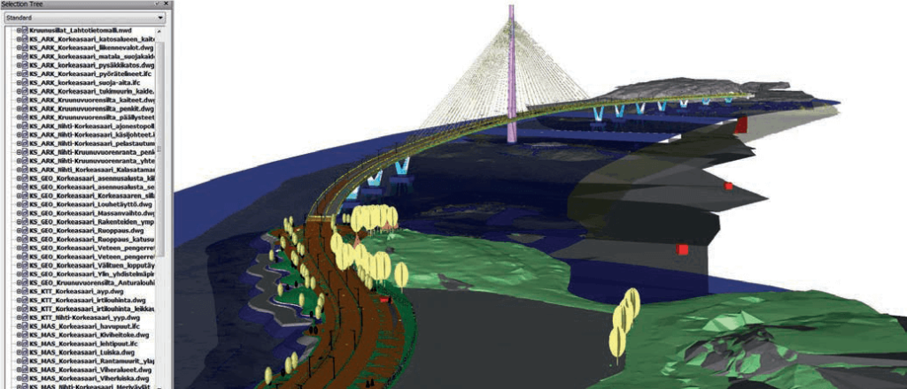
Multidisciplinary information modelling project
The city of Helsinki generally requests modelling as a design method and information models as deliverables in all of their infrastructure design projects. This project and the design appointment includes not only the bridge and other structures, but also street and tramline, landscape, environmental, lighting, municipal utilities, geotechnical, noise and vibration designs; all of these to be done and delivered model-based. The Authorities in Finland foresee that the selected design method, which may currently be a bit more challenging to proceed, time-consuming and expensive, will certainly payback during the lifetime of the structures. Having the information of existing structures in digital format when building new or maintaining old will then be valuable and save cost.
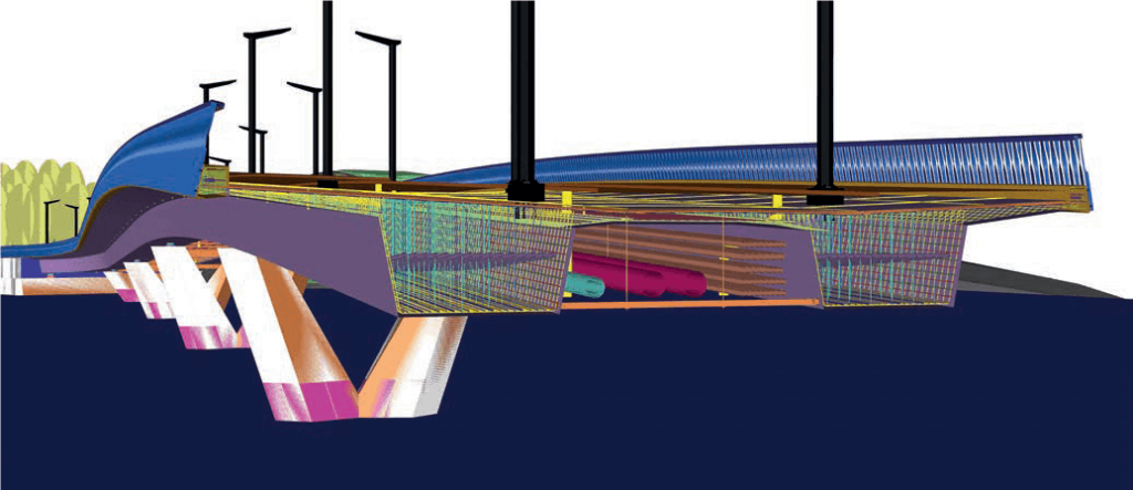
For the Kruunuvuori Bridge project, new design procedures had to be created. All the models are updated regularly and collected into the collaboration model. Collaboration models are then uploaded to the project server for use by project managers. Also, data records, including the contents, origin and quality of the data is of great importance. The amount of data continuously increases as the process goes into greater detail. Designs need to be well organized; it’s not practical to read all the designs in one model automatically.
Bridge reinforcement, for example, is exported into a separate model so that those who need it can upload it as required. Quality assurance of model-based designs is different both in its form and its tasks, as the designs are different from traditional ones. It was initially intended, that the updated cost estimates would be generated semi-automatically as models were updated, but ultimately it was discovered that tracing the real changes from the huge amount of data involves a significant amount of work. It is expected that these new procedures, currently in use, will develop over time.
Generally, the challenge in the design of multidisciplinary projects is that most applications are tailor-made for their specific design field and it is not easy or possible to import or export the information between disciplines. General and open formats are needed to collaborate as the direct data exchange is rarely possible. Even the different software packages only for bridge design do not talk to each other.
Design tool development
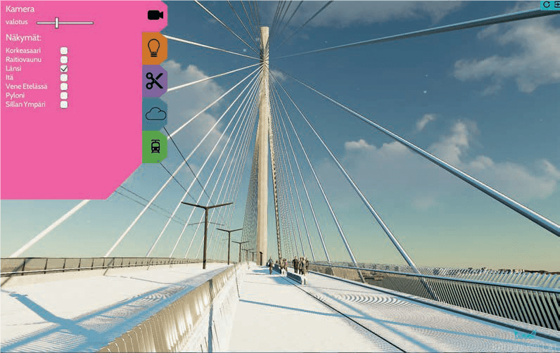
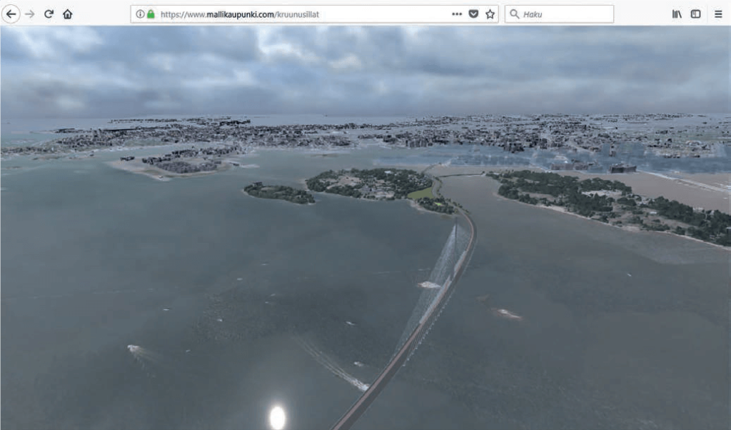
Addressing the challenge to find the best way of collaborating the different disciplines, and getting all the information together has also opened completely new possibilities such as visualisation of all the technical designs, mobile visualisation applications using GPS and a camera and 3D printing (e.g. for the wind tunnel testing model). Whatsmore, parametric design software and applications offer new, more powerful tools to designers.
Applied games technology was first used for lighting design on the bridge, but subsequently, a full model visual VR-game was created to present the designs to the public. Currently, the city provides not only maps, visualisations, videos, plans and reports, but also a 3D virtual model to show the project to the public. All of these have been made available to the public on the project web page (www.kruunusillat.fi).
Parametric design
Parametric design for information modelling has taken steps ahead due to software development as the new tools have been introduced. TEKLA has developed a “live link” application for the Grasshopper®, which is a RhinoCeros® plugin. Grasshopper allows comprehensive parametrization for the geometry (e.g. station based location for cross beams, construction joints, cable locations etc. with offset values to elevation line) as well for the structural components (tabulated plate thicknesses along the girder lines/axes) of the bridge. It has also easy to use geometrical functions for engineers (e.g.: “find a point where curve penetrates plane”, “find the closest points between two lines” etc…). These functions are practical in creating information model as well as creating the FE model, especially for the geometrically complex structures like Kruunuvuori Bridge. Also, in such projects like Kruunuvuori Bridge, where information model has established in early stages and updated regularly along the design development, this parametrization brings huge saves in modelling time. It also makes easy updates for the FE model possible as the same data can be read into the SOFiSTiK.
Construction stages and differences between the geometries for fabrication and for final structure has been a challenge for information modelling. The fabrication geometry is usually different (inclusive of precamber) from the final one. The geometry of the structure can be considered as a variable over the erection time. The final geometry of the structure can easily be used for geometry control at the site, as we know the difference from the designs.
Usually, a model with another geometry is needed for fabrication. There are modelling techniques on how the fabrication shape can be incorporated into the initial (final) geometry, but parametrization provides new possibilities to model different geometries over time.
Project status
The Engineering design for the Kruunuvuori Bridge is progressing as planned. All the designs for the Kruunuvuori Bridge are scheduled to be completed and submitted as proof checked to the client by the end of the year 2018. The design package including the Finke Bridge has already been submitted for the client. Independent proof checking for the designs, including the information model, is done by a third party A Insinöörit Ltd.
According to the client’s preliminary schedule, the tendering for the bridge contract is estimated to start in autumn 2020, while the construction is estimated to start in autumn 2021. The schedules are subject to change. Read more.
3 | Conclusion
Information modelling will come into the Bridge design, globally. It will take some more time before all the clients agree about or see the value of digitally modelled information. Anyway, it’s clear that there will be no turning back, especially in such Scandinavian countries like Finland and Sweden, where information modelling is widely applied. Developing countries will follow. There is a lot to develop in the software industry to make software easy to use, compatible and flexible so that the designs are easy prepare and easy to use. As the deliverables, results of the design work, look and are different, it also requires a different approach for design approvals, checking and requirements. There will be no structural drawings to approve in the future. Designers shall also rethink how their designs can be easiest but unambiguously given, without an unnecessary amount of work. Challenge is, especially in early-stage designs. There will be more new tasks for designers than fading old ones. Some of the clients foresee that the amount of the work is not increasing, the work will only be done in an earlier stage of the structures lifetime. There is also a great opportunity to develop completely new products and tools, as we have seen already. It is a great opportunity for the whole construction industry.
Sources
[1] Finnish Transport Agency, (2014) BIM Guidelines for Bridges, available in English from https://julkaisut.liikennevirasto.fi/pdf8/lo_2014-06eng_bim_guidelines_web.pdf
[2] City of Helsinki, city engineer’s office (2014), Taitorakenteiden tietomallinnusohje (guidelines for special structures, bridge and other infrastructural structures), available in Finnish from https://www.hel.fi/hel2/hkr/julkaisut/ohjeet/taitorakenteet_tietomallinnusohje.pdf
[3] BuildingSMART Finland, (2014) Common BIM requirements 2012, available in English from http://www.en.buildingsmart.kotisivukone.com/3
