Complex Structural Timber Design
Aqualagon-Village Nature Paris, JFA Architect (Paris)
Written and presented at the SOFiSTiK Seminar 2018 by:
Prof. Engineer Jean-Marc Weill | C&E Ingénierie
Summary:
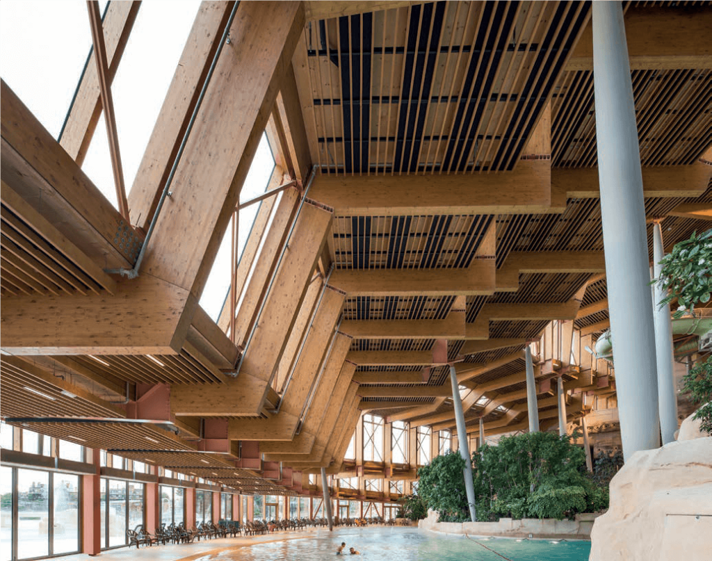
In the context of fitting out a holiday village at Marne-la-Vallée in Seine-et-Marne (France), “Les Villages Nature du Val d’Europe” entrusted the construction of the aquatic complex to the French architect Jacques Ferrier. From a general point of view the project comprises three separate entities: the water pavilion including swimming pools (110×80 m with a maximum height of 27 meters), the air pavilion including a tower with a height of 17 meters and the outdoor lagoon comprising pools creating a total bathing area of 2500 m2.
This article covers the analysis of the wood-steel accessible roof structure of the air pavilion and particularly the presentation of the assumptions adopted for the roof design. As a general view, the uniqueness of this so-called large span structure is not to be a form-finding analysis with the very typical idea to find the best ratio between the volume of material and the span. At the contrary, the shape of the surface is simply a consequence of its accessibility as a “promenade”. This situation has led to a very unusual level of complexity regarding the engineering design also maximize using a non-isotropic material such as wood.
The Article is broken down as follows:
A. Design process assumptions
B. Analysis of the stability
C. Model and calculation
D. Innovation in wood connections
1 Context of the water pavilion
Geometry and Elements
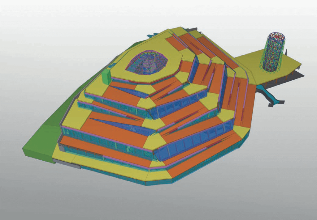
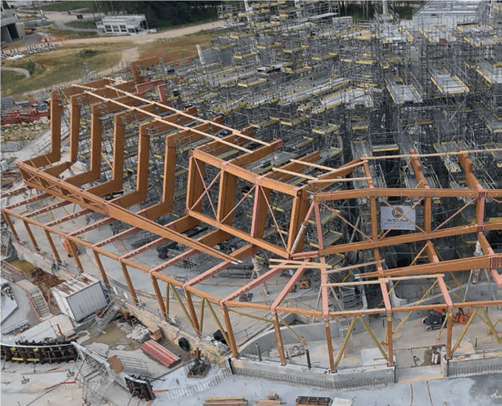
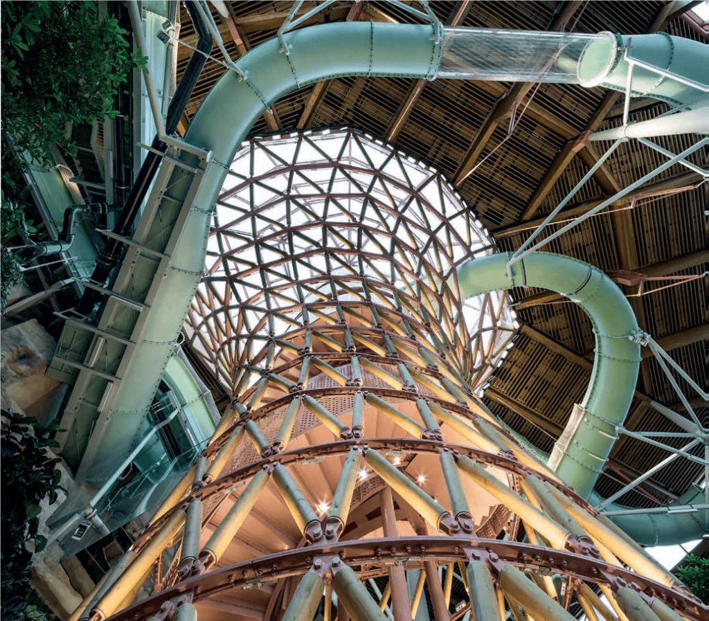
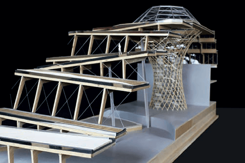
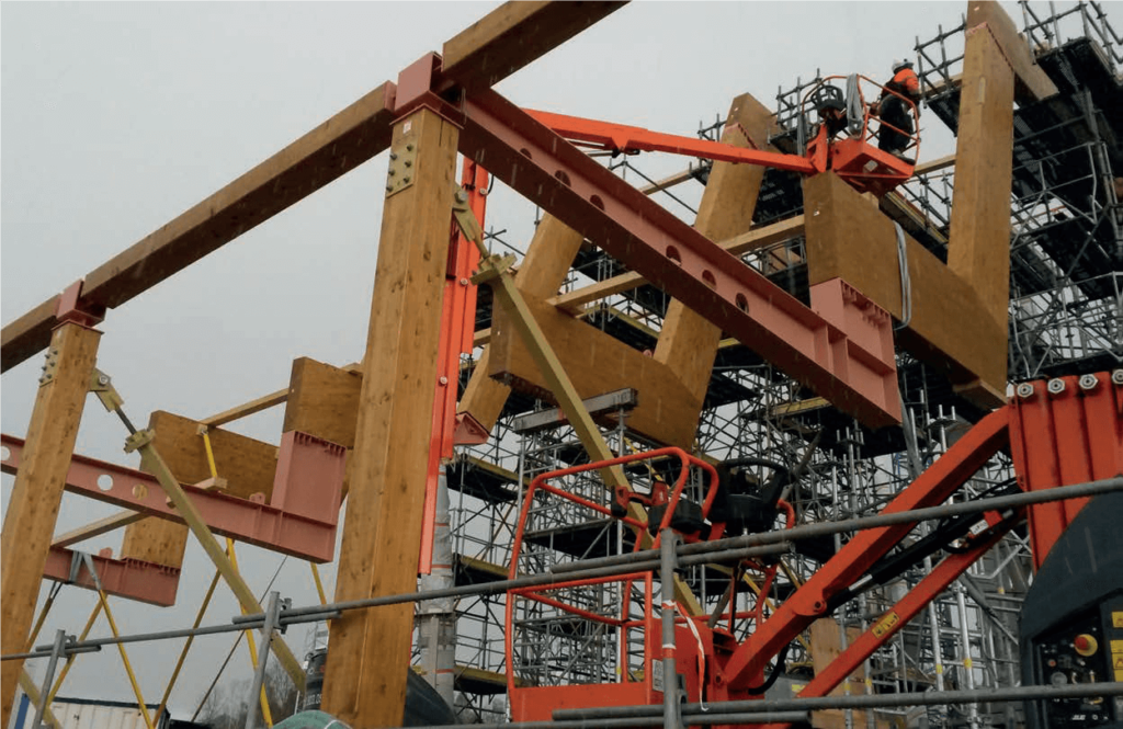
The project roof is a wood marquee “resting” on the surface to be covered. The marquee comprises a primary structure, consisting of a radiating frame and a second structure following the circumference of the main structure, with the result forming a random surface structure following the extension of the access ramps to the roof. On this hypothesis the primary structure is designed as follows:
Wood: laminated Glued wood Class GL24H / GL28H, according to the EN14080 standard NF or Cross Laminated timber KLH.
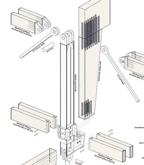
Formed mixed joists and wood studs Glued Laminated steel and triangulation forming a series of irregular truss beams. They are located behind the glass surfaces.
– Change heights: 60 cm to 650 cm
– Amplitude of the spans: up to 28 m
– Section of horizontal members: 2 x 150 x 400 mm
– Section of vertical members: 260 x 400 mm
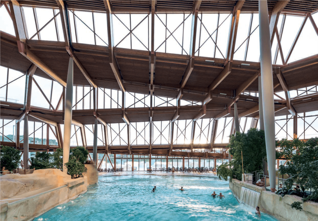
Radial beams made of laminated wood glued continuous floor-to the central core of the pavilion. Visible from inside the Aqualagon, these elements are located to the underside of the cover. Continuity is performed on-site with steelwork connection or at the factory by the implementation of glued studs. They participate in the stabilisation process producing the “shell” effect.
– Number: 52
– Maximum length: 45 m
– Section: 26 x 90 cm
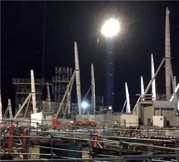
The structure of the roof rests on wooden posts on the front and on concrete High-Performance column located in and positioned by referring to the interior, that is to say, randomly accordingly random supporting structure of the roof.
The central core: the central element of the project, supporting a glass roof, the wooden ramp system and the staircase of access to water slides.
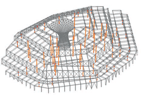
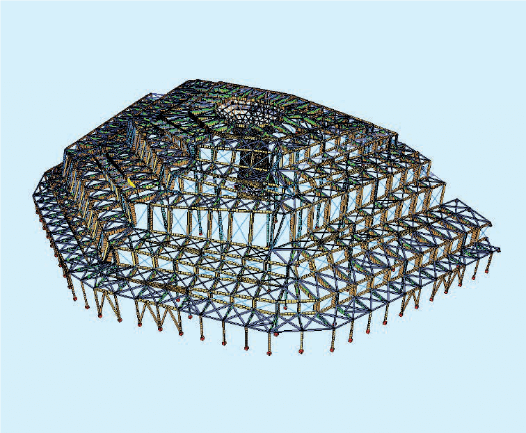
2 Modell
Input for calculation
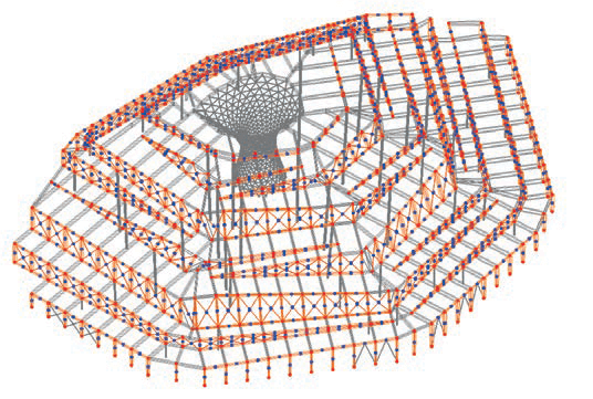
Modelling takes the form of a non-linear calculation conducted using the SOFiSTiK software application. The entire roof structure was modelled using bar elements except for interlocking beams at some ends of the truss beams, which were modelled using surface elements.
The following elements were used as input for the calculation model:
- Fibrous concrete posts: bi-articulated elements which only absorb normal forces.
- Truss beam upright and frames in glued laminated timber: continuous or articulated bar elements depending on the position. These elements support the windows which mean that the erecting tolerance of the curtain wall becomes the reference for the wood structure.
- Diagonal truss beams: steel tie rods.
- Radial glued laminated timber: continuous elements over one or several levels depending on the position of the resting points. The elements contribute to ensuring the stability of the roof shape and supporting the ramp decks. The calculation model incorporates the rigidity of the assembly. The elements are assembled with glued bolds.
- Decks in cross-laminated timber: the diaphragm effects of the deck are modelled using triangulations of wire elements in order to analyse the behaviour of the structure.
- Central drum: triangulated structure in glued laminated timber and horizontal steel straps.
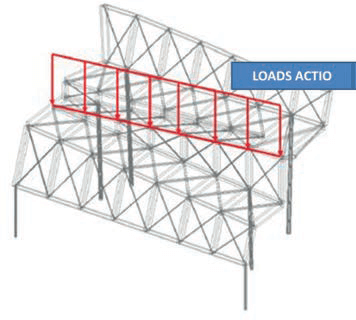
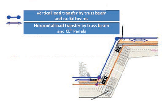
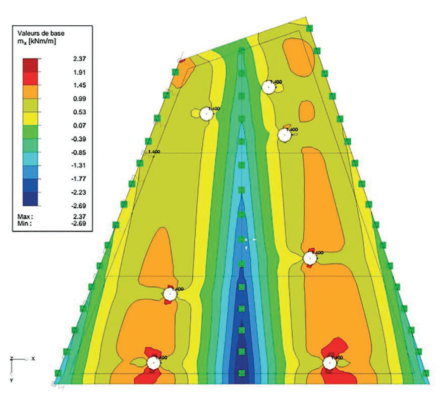
Shell effect
Outside the singular points, the transfer of vertical and horizontal loads to the foundation is done by the Association of the truss frame and the radial beams. The combination of the radial structure and trusses confers rigidity to the structure “shell effect”.
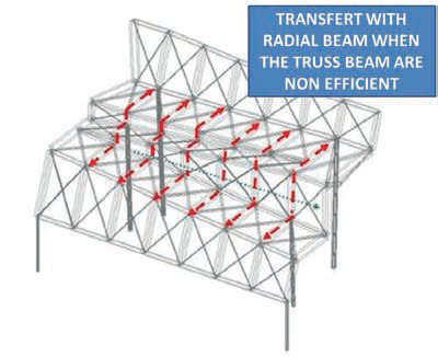
This stability plane is separated from the radial beams loaded to ensure the stable shape of the structure. Modelling is established on this basis. Horizontal forces are mainly transferred via the vertical stability support structures located in the lower part of the first ring and in the triangulated central drum. Vertical bracing is ensured by stability support structures positioned in the pool side of the façade and by the reinforced concrete structures hosting the equipment for the overall structure.
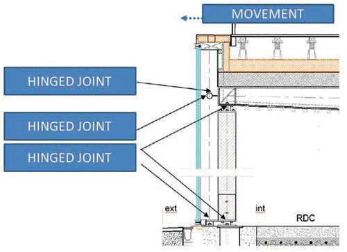
Thermal dilatation
Given its geometry, the roof is designed without expansion joints. It thus spans the infrastructure expansion joints in reinforced concrete. This assumption led to leave the free volume to expand out of its plane under the action of heat loads in particular, by placing on the ground floor facade pendulum columns for horizontal expansion. The facade of the Ground Floor is then designed to be fixed to the primary framework and follow the movements. At the rear of the building, the interface with the concrete block is done by sliding support for not curbing the expansion of the superstructure.
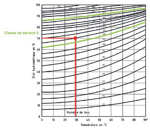
Wood service class strategy
The purpose of this chapter is to discuss the potential impacts caused by the change in wood service class (switch from class CS1 to class CS2 regarding Eurocode recommendations). This discussion was asked, on a conservative basis, by the Customer, regarding the typical interior humidity of such a program even if it was possible, from an analytical point of view, to retain the CS1.
The analysis had the following targets:
- Comparative analysis of stress variations in wood/steel sections after the change of service class.
- Analysis of the compatibility of the width of the windows and new strain in the truss beams supporting the windows in view of assembly slip and wood creep.
- Modification of the execution order subsequent to the change of class.
The change in service class will increase strain in the truss beams and their appropriateness for the dimensions of the windows. The curtain wall recommended is designed with stiffeners in glued laminated timber and aluminium mullions structures.
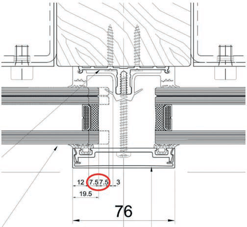
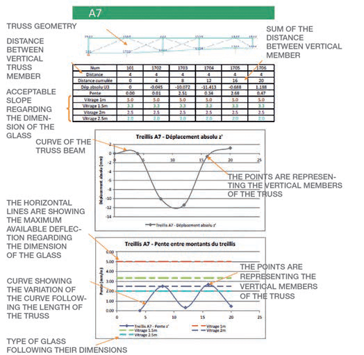
On a precautionary basis, the acceptable slope between two vertical members of the truss beam is limited to 5 mm per window. In order to apprehend the strain which the facade could absorb, we had to analyse two successive states of the wood frame:
- The strain of the truss beams before the installation of the windows Uinst, Gmin including the specific weight of the roof complex and the earth removed. This state will be our “reference point 0” when calculating the impact of strain on the windows.
- The final strain Ufin of the beam under full dead load (Gmax), Live Load (Q) and Snow Load (N)
The difference between the two stages is giving the strain value which the facade must absorb throughout the life of the building. This analysis is giving the acceptable dimension of the window length regarding the beam and the position on it.
- Punctual adaptation of the length of the windows planned during the project stage (reduction) on the basis of these results.
The main results obtained, on the basis of the model created by the design team, are as follows:
- The switch to service class CS2 only has a very moderate effect on forces in the building frame components and does not modify the sizing of the contract documents.
- The switch to service class CS2 punctually redistributes the lowering of loads between resting points by 15% (on the basis of the comparative analysis of the project management model). This value is substantially lower than the global increase coefficient integrated by the company for the transmission of lowering loads in order to integrate all possible modifications.
- The switch to service class CS2 and the integration of assembly stiffness affects the strain on truss beams, as expected. The width of a few windows must be reduced in order to globally comply with allowable rear structural gaps, limited at 5 mm by the company.
The modification inherent to switching to service class CS2 aggravates the factor Kdef (strain coefficient according to Eurocode 5). The coefficient is now 0.8 (versus the 0.6 initially planned for service class 1).
3 Focus on structural design
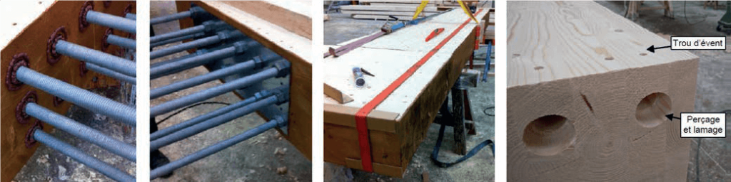
Assemblies by glued dowels
The assemblies by glued dowels concerns the assembly of radial beams. They used to reconstruct the geometric continuity of the assembled elements therefore like broken beams. This device is intended for assembly embodiment in new construction. The bonded stud system allows assembly of elements wood structure between them and with other structural elements. These assemblies can be subjected to axial loads and / or transverse.
The resins used for injection and pasting wooden steel rods are made on the same epoxy resin bi component tradename Eponal 316 TH, distributed by the company Bostik S.A. The manufacture beams and the sizing operation are carried out exclusively at the factory. The mechanical assembly of this type of performance is established on the basis of characterization tests. The studs are composed of a threaded rod, two nuts and a centering system. They are treated as required by the environment in which the implementation will be. For the construction of Aqualagon threaded rods and nuts are galvanized.
Machining is composed of a bore for the introduction of the threaded spindles, a countersink for the establishment of a centering nut, and two vent holes for the injection of the resin (an injection hole and a degassing hole of either side of the bore).
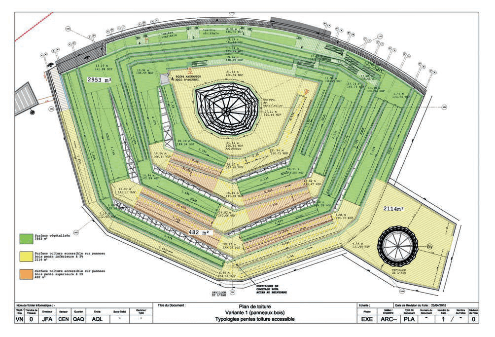
CLT panel gradients
When preparing the working drawings, the design and construction team suggested using KLH panel gradients incorporated in the solid base. The slope shapes of KLH panels in the solid base has no effect on the overall design of the support panels for the roof set-up. The panels, with a width of 240 cm, will have a 3% external gradient, reducing the low point section to a thickness of 190 mm.
When justifying the panel, we have assumed a minimum useful section with consideration of the upper and lower folds in the direction of load bearing between radial beams, i.e. 4 metres. The reduced section panel considered for the calculation is equivalent to a 162 mm panel (and not 190 mm) in order to correspond to the DTA (Technical approval) for the product.
4 Conclusions and Acknowledgements
This document covers the analysis of the wood-steel accessible roof structure of the air pavilion and particularly the presentation of the assumptions adopted for the roof design.
As a general view the uniqueness of this so-called large span structure is not to be a form-finding analysis with the very typical idea to find the best ratio between the volume of material and the span.
At the contrary the shape of the surface is simply a consequence of its accessibility as a “promenade”. This situation has led to a very unusual level of complexity regarding the engineering design also maximize by the use of a non-isotropic material such as wood. At the end of the design process the real complexity of the structural system is to be at the same time an accessible slab and a roof in a very humid atmosphere which might improve the structural design.
From more than anything else this very ambitious project was a success because of the exceptional attitude from some members of the design team. I would like then to express my gratitude to:
Agence architecture Jacques Ferrier, Architect, Professor Wolfgang Winter (ITI Wien), Civil Engineer Henry Bardsley, SOFiSTiK support team, Wood general contractor Arbonis, Wood KLH contractor Lignatec Thomas Baehrel, French “Centre Scientifique et Technique du Batiment”, Laboratory Efectis for the fire analysis.
