Automation with SOFiSTiK Templates – How to Save Time and Reduce Clicks by Using Templates
Written by Dipl.-Ing. Mikhail Nazarov, LLC “APEX project bureau”
Introduction
The idea of templates to create efficient workflows and speed up engineers’ daily work routines is widely used in BIM design tools such as Autodesk Revit.
But it’s still something new for structural calculation software packages. The engineer must go through numerous dialogue boxes and lots of mouse clicks to complete the analysis. And if something changes, it has to be repeated over again for every single iteration.
At APEX Project Bureau, we developed the technology to carry out structural analysis with impressive speed. And the key is using SOFiSTiK templates as it is the only finite analysis program, as I know, providing the engineer with the capability of “templatization”.
Let’s take a closer look at how it works.
Model preparation
First of all, the analytical model gets prepared. We use Revit as a preprocessor since it’s very convenient for modelling and project coordination. And since our Revit models are cloud-based, collaborating with other companies on our models is possible.
In Revit, the following is defined:
- Geometry and sections
- Structural materials
- Load cases and loads (most used load cases are already defined in our template, so no need to define them every time)
- Hinges (if needed)
- Groups
For further automation in SOFiSTiK, it is crucial to use standard rules, names and numbers for groups, load cases, etc. Those rules are described in the company BIM standard.
System export
After completing the model in Autodesk Revit, we export the entire system and subsystems to open the generated files in SOFiSTiK Structural Desktop with our templates applied.
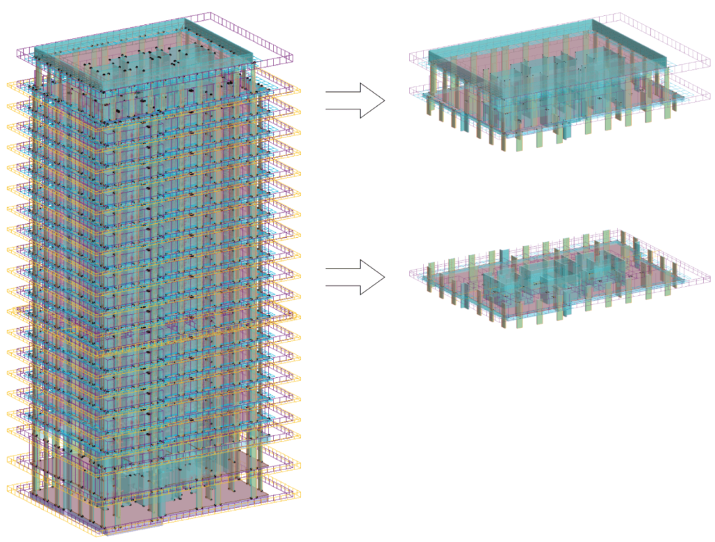
For a typical reinforced concrete residential building, we created two templates:
- For subsystem/slab analysis (plate template)
- For the global system analysis (building template)
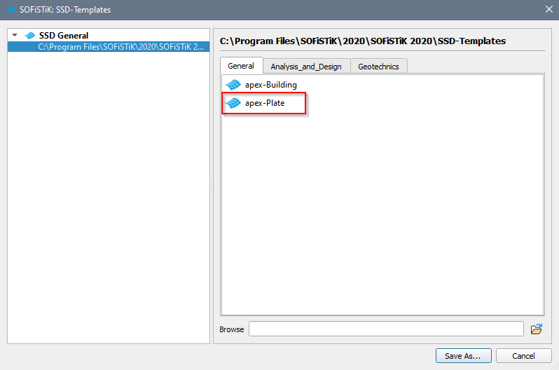
Plate analysis template (Subsystem/Slab)
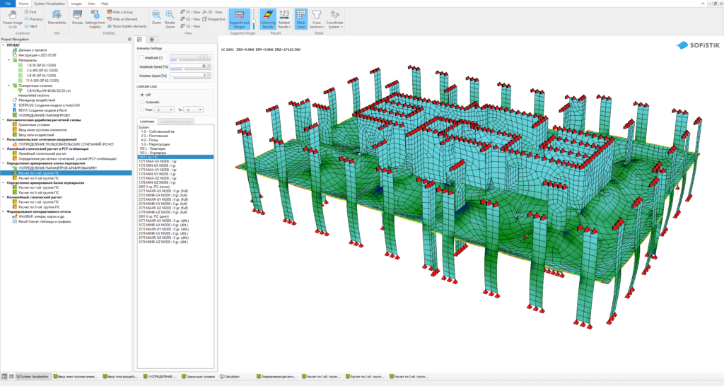
Let’s look into the first created template to analyze subsystems – the “apex-Plate” template.
In the Project navigation on the left, you can find the taskbar packed with predefined tasks. Most of them are text input tasks as they offer a higher level of automation capabilities and control of the calculation process.
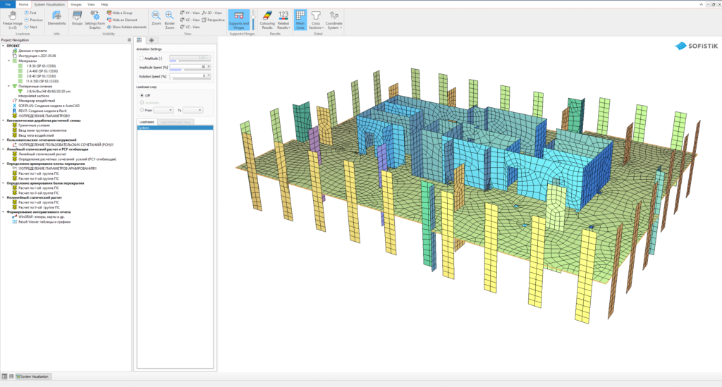
Some tasks such as linear and nonlinear analysis, ULS and SLS slab design are standard graphical tasks converted into the text input. However, other tasks are unique and user-defined. For instance, to add boundary conditions for upper and lower nodes of subsystems. Those boundaries are required to create a stable system and ensure correct structural behaviour.
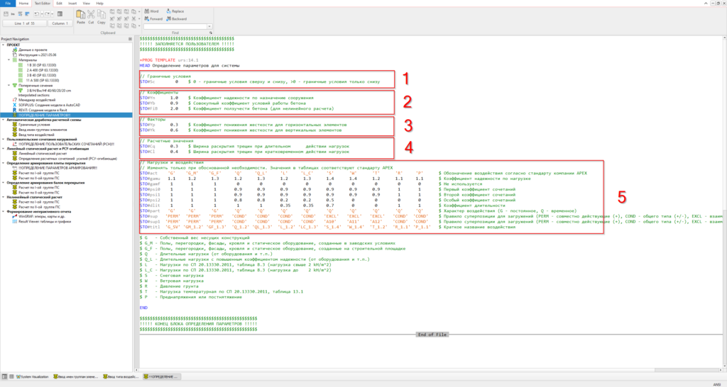
To perform the analysis, the user has to open a task called “parameters definition”.
The script of this template programme module includes all variables (#STO global variables) which control the entire calculation and represent the whole idea of “templatization.”
The engineer has to check and adjust the defined values if required.
The parameters specified are:
- Input to choose if the boundary conditions are to be appended to lower nodes or both lower and upper nodes. The first option is used if we analyze the roof.
- Design coefficients for materials
- Stiffness factors for horizontal and vertical structures
- Limitation of maximum crack width for ULS/SLS design
- Table to match actions with the corresponding partial safety factors (GAMU, GAMF) and combination coefficients (PSI0…PSI2). All those numbers are aligned with our building design regulations. The user doesn’t change this data unless he wants to use a different design code.
Usually, it takes one minute to take a quick look at the “parameters definition” task to double-check the input values or, if necessary, to adjust them.
After the “parameters definition” task, the model gets prepared for further analysis. It includes adding boundary conditions, group names and assign all safety factors and combination coefficients to actions.
The standard task “combine loads” follows to define manual ULS and SLS load combinations for further nonlinear analysis.
After completing the preparation of the project, we are ready to run the complete analysis procedure by hitting the magic button “calculate all”.
The analysis includes:
- Linear analysis
- Load superposition for design
- Slab design ULS/SLS
- Beams design ULS/SLS
- Nonlinear slab analysis
Material nonlinearity is activated by the ASE input line SYST PROB NONL NMAT YES during the analysis. The program iteratively calculates the manually defined load combinations and allows to estimate slab deformations more precisely. Moreover, it gives access to nonlinear results such as crack width, the stress in reinforcement etc.
After the calculation finishes, it’s time to review the results. The Interactive Graphics (WinGRAF) task includes a predefined set of sheets and graphics with all necessary information about the slab such as loads, internal forces, deflections, punching forces, theoretical reinforcement distribution etc.
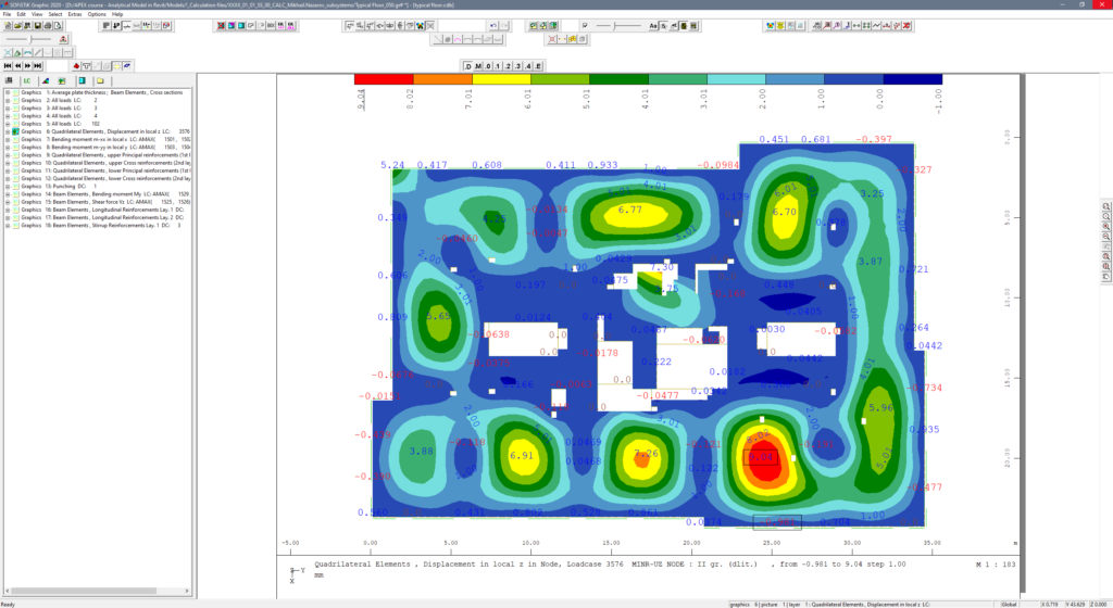
With the results available as nice colourful pictures, the actual engineering work starts. We have to comprehend the output and conclude if the results are reasonable and OK. If not, amends are required, and the model has to be recalculated. Thanks to using templates, this takes only a few minutes.
Building analysis template (Global Analysis)
The idea of the second template is similar to the subsystem template. However, the amount of variables is more extensive since the analysis itself is more complex.
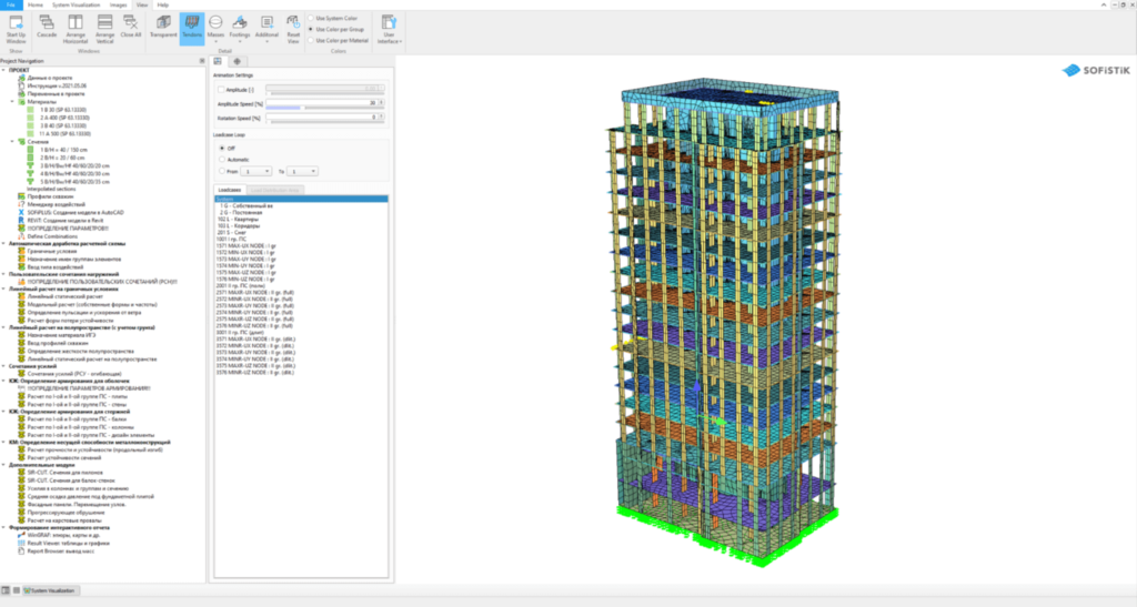
The main steps are the following:
- Automatic model preparation – similar to the plate template. But the boundary conditions are defined for the foundation.
- Load combinations
- Linear analysis with boundary conditions
- Modal analysis
- Wind loads analysis, including spectral analysis for the dynamic part
- Linear buckling analysis
- Half-space analysis for soil-structure interaction
- Load superposition
- Slab design
- Wall design
- Beam design
- Column design
Only Step 2 requires action by the user; all other steps are fully automatic.
Conclusion
The main idea of “templatization” is saving time and reducing mouse clicks for typical model calculation. Although it takes some effort to write the script and make it work properly and, of course, not to forget maintaining the code after SOFiSTiK updates – because as a rule, some critical errors always appear 🙂 – it is worth it.
Templates save a tremendous amount of time in recalculating the model as many times as needed to find the best solution for the project. Templates also reduce the number of potential mistakes caused by the user.
As initially mentioned, achieving such automation is only possible by using standard rules of naming and numbering in all your models.
Documented in BIM standards or separate guides, every engineer in your company must follow those rules to create efficient workflows and speed up daily work routines.
Read also: Integration Between of Calculation Modelling & Building Information Modelling
