Automated Design Work of Precast Concrete Girder Viaducts
Written and presented at the SOFiSTiK Seminar 2018 by:
Kees van IJselmuijden BSc PMSE | Royal HaskoningDHV
Summary
In this paper, we describe the way of working on an automated process for making a model in Revit®. The automation is based on the standard prefabricated viaducts that are built in the Netherlands. From the Revit model, we go directly to the SOFiSTiK model.
1 | Introduction
In the Netherlands, more than 80% of the viaducts are built with pre-cast girders. The pre-cast girders are calculated and designed by the suppliers. On the internet, you can find the type of girder (height, weight, etc.) related to the span, from all the diffe¬rent suppliers. So, for a structural bridge engineer, this work is not really challenging. Your only job is to calculate the abutments and piers.
When you work with a contractor, in the tender phase you want to model in a short time different options. In the preliminary design phase, the girder supplier is always chosen when you are almost finished with your design. So, we need to make basic models for tenders quite fast and in the preliminary design, we need to be able to change the model in a very late stage of the design. The conclusion we designers are always under pressure.
In March 2016, we discussed in a small group how we good deal with this issue. During this discussi¬on, the idea of making a tool for automated design is born. The goal of the idea was to get a fast model in the tender phase in Revit and a first model for the preliminary phase that covers already 80% of the whole model. Together with this we also wanted directly a model that can be used for calculations and totally the something that makes hour work more attractive. With an enthusiastic group of en¬gineers and the support of Autodesk, we managed to create a model of a viaduct in 10 minutes.
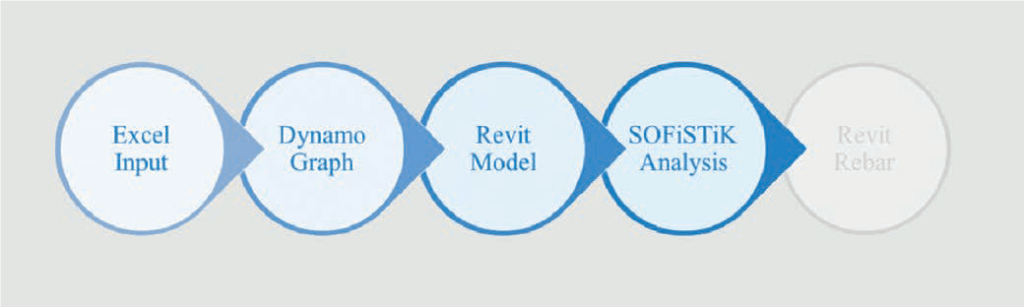
2 | Workflow
To organize the way of working we first organized the workflow and also, we described what the result of the outcome should be. This was really important to do because sometimes you want to make no compromises that result in the end for even more work or a tool that no one is going to use. So, it was my job to push the team and also Autodesk to the limit.
And we build the workflow shown in figure 1.
3 | Input Excel
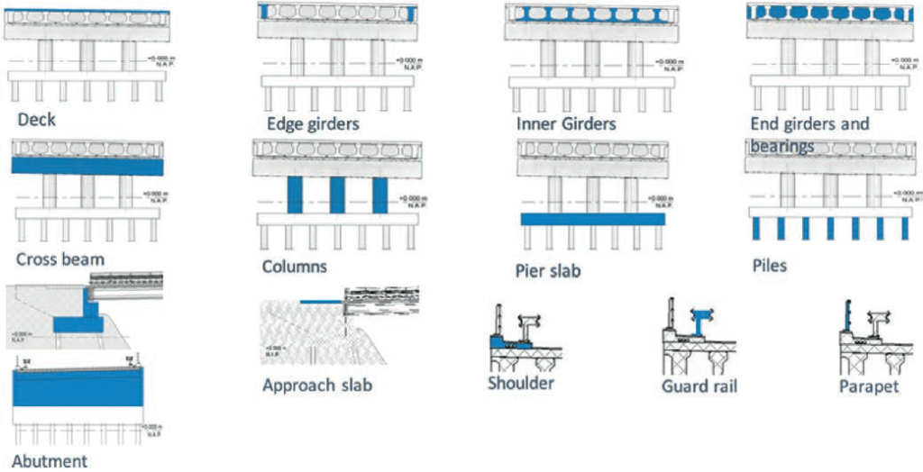
After we organized the workflow we needed to decide what we wanted to be parameterised and what 43 would be standard and not able to change. In Figure 2, the parametric elements for the viaduct are shown.
All needed values for the different elements are placed in an excel to fill in. Of course, we also needed to place the model somewhere in the world. And we needed to think about how we decide what span we needed to take into account.
We started with straight viaducts, where we placed the length of the centrelines between the piers and abutments, starting at the first abutment. We limited the excel for now to place a maximum of 10 spans. Later we also organized a curved viaduct with the input of a Json file. In the Json file, we store with a graphic interface for the spans and the asphalt corridor, based on the Civil 3D or MX model (text files with x-, y- and z-coordinates).
4 | Dynamo
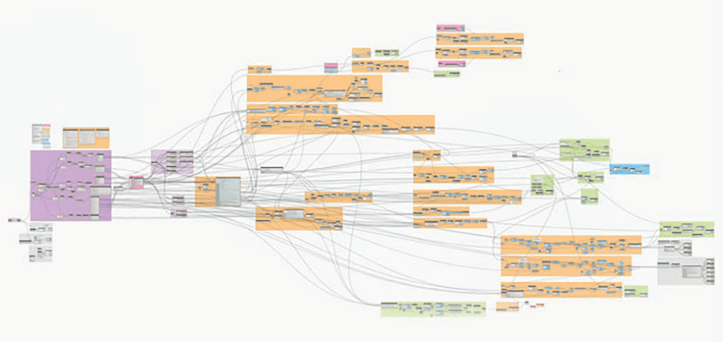
After we saved the excel input file, we can go to Revit and open Dynamo. With Dynamo, we organized all the relations of the elements and family’s that are placed in the Revit 3D model.
The total Dynamo script was first quite long, but with more Python programming we managed to reduce the length of the script and time for running the script. An example of how the script looks like is shown in Figure 3.
5 | Revit
If you run Dynamo in Revit a 3D wire model will be shown in Dynamo and if you go than to Revit you see the full 3D Revit model. In Figure 4, you see a small part of the viaduct with all the relations and Revit properties.
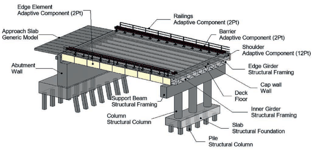
As can be seen, the Revit model is build up with all the viaduct elements and it is still a Revit model. You can change all parts in this model as you want (with the limits of Revit). To have such a model in 10 minutes makes it easy to see if there are clashes with other structures and if the clearance under the bridge is good enough. You can also see quite fast if the piers are on the right place or that you want them to be under an angle (following the road under the viaduct). You just make some changes in the excel and run the script again (and get some coffee for your colleagues). When you all decided that this is the right model, you can start making up the dra¬wings to get the old fashion 2D drawings.
6 | SOFiSTiK
If the model of the viaduct is frozen, we can start with the calculations. The nice thing about the mo¬del we made by Dynamo in Revit is that we made structural elements. When you switch to the structu¬ral view in Revit you will see the structural elements in your model. See Figure 5.
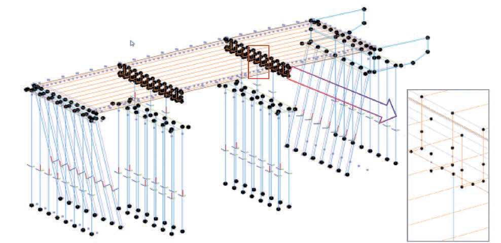
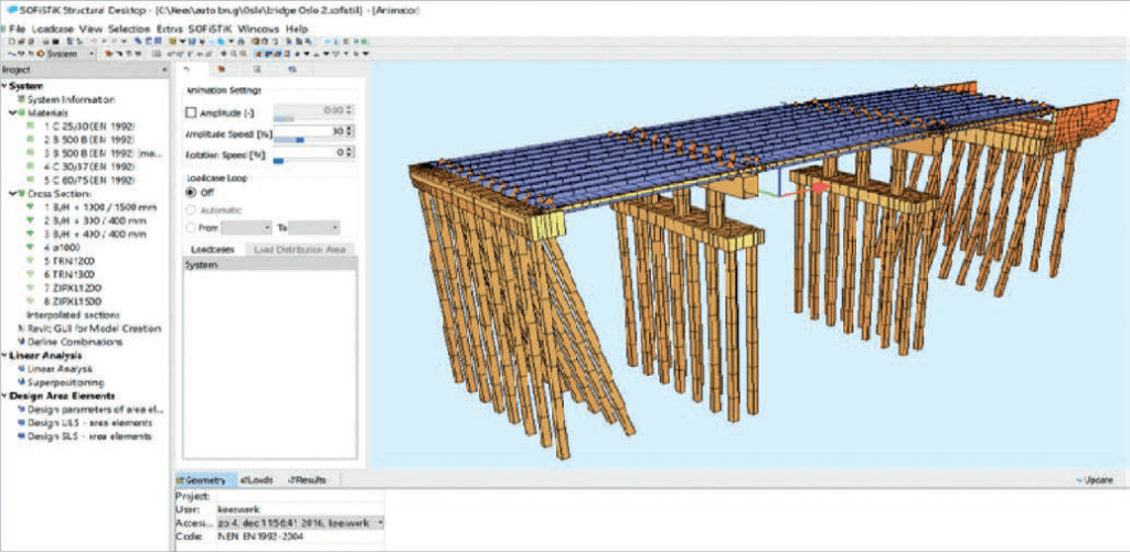
You see all the points, beams, columns, walls and plates. You can also see some extra points and beams created to connect the superstructure with the substructure. You can also see, that the connection is made on the top of the beams. This is because we choose in Revit to places analytical system line on top of the girder to connect with the floor. Unfortunately, Revit is designed for buildings and not for bridges and the export to SOFiSTiK is still in progress. But we had to deal with this and we made it right with some clicks (or make a script of it). If you have installed SOFiSTiK on your com¬puter, in Revit extra options are shown. Click on the SOFiSTiK menu and transfer/export the model to SOFiSTiK and run SOFiSTiK. In Figure 6 you see an export example to SOFiSTiK.
Note: We started with the Revit and SOFiSTiK | 2016 version. In this version Revit has its limits, we will investigate the Revit/SOFiSTiK | 2018 version soon.
A lot of things went well, but after a lot of time and pressure, we decided to get back to SOFiPLUS(-X) because of the limits in Revit. The following ele¬ments could not be created in Revit; Elastic links, hollow sections, free loads and imposed strains and bore profiles. Of course, these elements can be created with TEDDY but this requires much more experience of SOFiSTiK. This decision to go back to SOFiPLUS(-X) also excluded that we could not go back to Revit with the reinforcement results. We normally have an edge element that is a box-girder. The box-girder is hollow in the middle and solid in the ends. SOFiSTiK | 2016 was not able to export the different sections of the girder as modelled in Revit. In the project, we also had an abutment wall under an angle, that is not possible to model as a structural element in Revit. It is still our ambition to do this and we know that SOFiSTiK | 2018 has more possibilities. This can have an influence on the work¬flow as we have now.
In SOFiSTiK we made the necessary TEDDY files to calculate the structure. For the next bridge, we can reuse almost 90% of it.
7 | Conclusion
It took us some time to get the idea to reality and it helped that we are now using the tool in a real project. The first project went well until the changes came and all is handwork again. We see more potential in this way of working also for projects with not much repetition. If Revit can work as a pre-processor with the same capability as ACAD (also for variable cross-sections), it will be perfect. Until then we need to be creative.
